Acelerometro digital adxl345

hola a todos
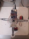
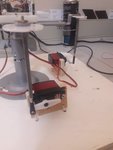
necesito realizar un sistema que mida los grados de inclinación en los tres ejes, para ello
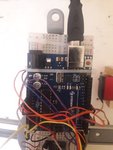
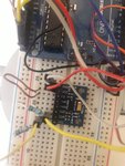
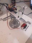
adquirí un acelerómetro adxl345 que se configura por medio de i2c, como microcontorlador he usado un 16f877a para leer los datos y poder procesarlos, he logrado comunicarlo con el pic, sin embargo no me toma lecturas negativas, la concatenación la estoy realizando como dice en la pagina de fabricante, agradecería cualquier aporte
Código:
#include <16f877a.h>
#fuses XT,NOWDT,NOPROTECT,PUT,NOBROWNOUT,NOLVP
#use delay(clock=4M)
#include <stdlib.h>
#include <math.h>
#include <stdio.h>
#include <lcd.c>
#use i2c(MASTER, SDA=PIN_c4, SCL=PIN_c3,FORCE_HW)

#define ACCEL_WRITE_ADDR  0XA6//0xA6 //0x53//0x3a
#define ACCEL_READ_ADDR  0XA7//0xA7  //0x53//0x3b
#define ACCEL_DATA_ADDR 0x32
#define ACCEL_PWRCTRL_ADDR 0x2d
#define ACCEL_MEASURE_MODE 0x08

   unsigned int accel_data[6];
   unsigned int16 x,y,z;
   float x1,y1,z1,R;
  float teta=0, gama=0,fi=0;

void main ()
{
  enable_interrupts(int_rda);
  enable_interrupts(GLOBAL);

   // initialize

   while(true) {
     lcd_init();

      // Tell the accelerometer to wake up
      i2c_start();
      i2c_write(ACCEL_WRITE_ADDR);
      i2c_write(0X31);
      i2c_write(0X01);
      i2c_stop();

     I2C_start();
     i2c_write(ACCEL_WRITE_ADDR);
     i2c_write(ACCEL_PWRCTRL_ADDR);
     i2c_write(ACCEL_MEASURE_MODE);
     I2C_stop();


      // Read data from the accel
      i2c_start();
      i2c_write(ACCEL_WRITE_ADDR);
      i2c_write(ACCEL_DATA_ADDR);
      i2c_start();
      i2c_write(ACCEL_READ_ADDR);
      accel_data[0] = i2c_read(); //x0
      accel_data[1] = i2c_read(); //x1
      accel_data[2] = i2c_read(); //y0
      accel_data[3] = i2c_read(); //y1
      accel_data[4] = i2c_read(); //z0
      accel_data[5] = i2c_read(0); // z1, NACK on last read
      i2c_stop();
      //////////concatenar datos adxl345/////////////
      x=((accel_data[1])<<8)|accel_data[0] ;
      y=((accel_data[3])<<8)|accel_data[2];
      z=((accel_data[5])<<8)|accel_data[4];


      x1=(float)x/256;
      y1=(float)y/256;
      z1=(float)z/256;
      ////////////////////////////////////////////////
      R=sqrt((x1*x1)+(y1*y1)+(z1*z1));


      teta=acos(x1/R);
      teta=teta * 57,296;

      gama=acos(y1/R);
      gama=gama*57,296;

      fi=acos(z1/R);
      fi=fi*57,296;


     printf(lcd_putc,"\f %.2f %.2f %.2f ",x1,y1,z1);
     printf(lcd_putc,"\n %f %f %f ",teta,gama,fi);

   }
}
 
Última edición por un moderador:
Hola, viendo rapidamente te puedo aportar que declaras solo variables unsigned int (accel_data[6],x,y,z) en las cuales almacenas y operas datos recibidos del dispositivo, por lo tanto solo puedes obtener valores positivos.
 
hola de nuevo,
necesito obtener el angulo entre la horizontal y el suelo pero no lo he logrado...agrego el codigo para ver si existe lgun error, lei la AN1057 Y segui sus indicaciones pero no ha funcionado...
de nuevo mil gracias.

Código:
#include <16f877a.h>
#fuses xt,NOWDT,NOPROTECT,PUT,NOBROWNOUT,NOLVP
#use delay(clock=4M)
#include <stdlib.h>
#include <math.h>
#include <stdio.h>
#include <lcd.c>
#use i2c(MASTER, SDA=PIN_c4, SCL=PIN_c3)


#define ACCEL_WRITE_ADDR  0XA6//0xA6 //0x53//0x3a
#define ACCEL_READ_ADDR  0XA7//0xA7  //0x53//0x3b
#define ACCEL_DATA_ADDR 0x32
#define ACCEL_PWRCTRL_ADDR 0x2d
#define ACCEL_MEASURE_MODE 0x08

   signed int accel_data[6];
   signed int16 x,y,z;
   float x1,y1,z1,R1,R2,R3;
   float teta=0, gama=0, fi=0;
   float teta1=0, gama1=0 , fi1=0 ;
   signed int16 AX,AY,AZ;

void main ()
{
    // initialize

   while(true) {
     lcd_init();

      // Tell the accelerometer to wake up
      i2c_start();
      i2c_write(ACCEL_WRITE_ADDR);
      i2c_write(0X31);
      i2c_write(0X0B);////+-16
    //i2c_write(0X01);///+-4g
      i2c_stop();

     I2C_start();
     i2c_write(ACCEL_WRITE_ADDR);
     i2c_write(ACCEL_PWRCTRL_ADDR);
     i2c_write(ACCEL_MEASURE_MODE);
     I2C_stop();


      // Read data from the accel
      i2c_start();
      i2c_write(ACCEL_WRITE_ADDR);
      i2c_write(ACCEL_DATA_ADDR);
      i2c_start();
      i2c_write(ACCEL_READ_ADDR);
      accel_data[0] = i2c_read(); //x0
      accel_data[1] = i2c_read(); //x1
      accel_data[2] = i2c_read(); //y0
      accel_data[3] = i2c_read(); //y1
      accel_data[4] = i2c_read(); //z0
      accel_data[5] = i2c_read(0); // z1, NACK on last read
      i2c_stop();
      //////////concatenar datos adxl345/////////////
      x=((accel_data[1])<<8)|accel_data[0] ;
      y=((accel_data[3])<<8)|accel_data[2];
      z=((accel_data[5])<<8)|accel_data[4];


//////////////////////////multiplicar 16*2/2^13//////////////////
      x1=(float)x * 0.00390625;
      y1=(float)y * 0.00390625;
      z1=(float)z * 0.00390625;
      ////////////////////////////////////////////////
   //   R=sqrt((x1*x1)+(y1*y1)+(z1*z1));


      R1=sqrt((y1*y1)+(z1*z1));
      R2=sqrt((x1*x1)+(z1*z1));
      R1=sqrt((y1*y1)+(x1*x1));


    // teta=acos(x1/R);
     teta=atan(x1/R1);
     teta=teta * 57,296;

//      gama=acos(y1/R);
      gama=atan(y1/R2);
      gama=gama*57,296;

//      fi=acos(z1/R);
        fi= atan(R3/z1);
        fi=fi*57,296;

AX=(TETA*10)*0.1;
AY=(GAMA*10)*0.1;
AZ=(FI*10)*0.1;

 printf(lcd_putc,"\f %ld %ld %ld ",x,y,z);
printf(lcd_putc,"\n %LD %LD %LD ",AX,AY,AZ);
DELAY_MS(100);

   }
}
 
Última edición por un moderador:
Amigo yo tambien estoy interesado en este proyecto del acelerometro ya que yo tengo que mover unos motores con respecto a la posicion del acelerometro.
Desearia tu ayuda
 
Hola, curiosamente este acelerometro me fallo dos veces, la primera cuando estaba integrado con un giroscopio(IMU), la segundo como independiente es decir,
poseia el mismo problema, la medida leida en el bus de comunicaciones despues de concatenarla era por ejemplo de -25, de ese valor se saltaba a 220(+-8 bits), no pude entender porque, lo que hice fue usar un acelerómetro que en vez de I2C usara directamente los pines CAD de un microcontrolador, usÉ el MMA7361L, puedes encontrar una muy buena guía buscando en
starlino IMU
vale la pena mencionar que si optas por un sistema I2C y tu sensor funciona a 3.3V y tu microcontrolador funciona a 5v debes realizar un sistema que acople tensiones o podrias averiar el sensor, puedes buscar por la AN97055 DE PHILIPS...
EXITOS...
 
¿Tu ya has usado ese AN97055? ¿Y que probabilidad de que ya no haya ese error ahí?
¿Podrías explicarme de que manera lo acoplaría?

Explícame estas expresiones que has puesto.

#define ACCEL_DATA_ADDR 0x32
#define ACCEL_PWRCTRL_ADDR 0x2d
#define ACCEL_MEASURE_MODE 0x08

¿Por qué motivo has puesto estas definiciones con esos determinados valores?
 
Última edición por un moderador:
EL AN97055 SI lo he usado, no es difícil el montaje, buscalo que hay aparece explicado detalladamente el circuito a usar, lo segundo

#define ACCEL_DATA_ADDR 0x32
#define ACCEL_PWRCTRL_ADDR 0x2d
#define ACCEL_MEASURE_MODE 0x08
son las direcciones de los registros del adxl345 para realizar la configuración, es necesario que leas el Datasheet, para entender el proceso de escritura y lectura.
 
Con respecto a las conexiones yo he hecho esto:
- sdo y gnd a tierra
- cs y vcc a alimentacion(3.16v)
- cls he puesto una resistencia(1k) a vcc(3.16v)
y tambien del cls a pin_c3
- sda he puesto una resistencia(1k) a vcc(3.16v)
y tambien del sda a pin_c4

¿corrigeme si las conexiones que he hecho esta bien?
 
Hola buenas tardes a todos los compañeros del foro.

Quiero compartir un pequeño proyecto que realice, pero al mismo tiempo pedir ayuda para el siguiente paso que busco del mismo.

Se trata de un circuito en arduino que utiliza el acelerometro ADXL345 y dos servomotores, uno para eje "x" y otro para eje "y".

He logrado que los servos sigan las posiciones en los ejes respectivamente. A continuación les presento el codigo que estoy utilizando:

C++:
/*

Conexion entre acelerometro y arduino:


Arduino     Accelerometer ADXL345

  A5            SCL

  A4            SDA

  3.3V          CS

  3.3V          VCC

  GND           GND


Conexión de servomotores:

Arduino     Servo No. 1

  5V          5V 

  GND         GND

  D9          CTRL


Arduino     Servo No. 2

  5V          5V 

  GND         GND

  D6          CTRL

*/


#include <Wire.h>

#include <ADXL345.h>

#include <Servo.h>


Servo servo1;

Servo servo2;


ADXL345 adxl;


int x, y, z;

int rawX, rawY;

int mappedRawX, mappedRawY;


void setup() {


  Serial.begin(115200);

  adxl.powerOn();

  servo1.attach(9);

  servo2.attach(6);

  servo1.write(90);

  servo2.write(90);

}


void loop() {

  adxl.readAccel(&x, &y, &z); //aqui se leen los valores del acelerometro y se guardan en variables x y z


  if (rawX < -255) rawX = -255; else if (rawX > 255) rawX = 255;   // aqui se definen los rangos  a utilizar

  if (rawY < -255) rawY = -255; else if (rawY > 255) rawY = 255;


  mappedRawX = map(rawX, -255, 255, 0, 180);    // en este apartado se hace la conversion a grados para que el servo lo entienda

  mappedRawY = map(rawY, -255, 255, 0, 180);   


      servo1.write(mappedRawX);

      delay(15);

      servo2.write(mappedRawY);

      delay(15);

}


Estoy utilizando dos servomotores DS8711.

Lo que ahora busco y solicito su ayuda, es como hacer que esta plataforma se encuentre siempre nivelada, es decir, que los servomotores actuen para que los ejes "x" y "y" siempre esten en 90 grados. Si pudieran ayudarme con el codigo se los agradeceria mucho. De hecho ya les agradezco por su tiempo.

Aqui pueden ver las fotos adjuntas

Saludos a todos.
 

Adjuntos

  • WhatsApp Image 2018-06-18 at 16.03.20.jpeg
    WhatsApp Image 2018-06-18 at 16.03.20.jpeg
    53.3 KB · Visitas: 11
  • WhatsApp Image 2018-06-18 at 16.03.21 (1).jpeg
    WhatsApp Image 2018-06-18 at 16.03.21 (1).jpeg
    47.1 KB · Visitas: 11
  • WhatsApp Image 2018-06-18 at 16.03.21 (2).jpeg
    WhatsApp Image 2018-06-18 at 16.03.21 (2).jpeg
    71.6 KB · Visitas: 9
  • WhatsApp Image 2018-06-18 at 16.03.21 (3).jpeg
    WhatsApp Image 2018-06-18 at 16.03.21 (3).jpeg
    82 KB · Visitas: 10
  • WhatsApp Image 2018-06-18 at 16.03.21.jpeg
    WhatsApp Image 2018-06-18 at 16.03.21.jpeg
    54.2 KB · Visitas: 9
Hola,

A ver si podeis echarme una mano con un sensor ADXL345 (acelerometro).
Quiero que detecte free-fall. La libreria SparkFun_ADXL345 proporciona esos metodos. Para ello, utiliza interrupciones.. Lo he conectado a arduino y se comunica bien (I2c) y funciona detectando tap, doble tap...., pero no detecta lo que quiero...tenog dudas.. este es el ejemplo
Código:
/*  ********************************************* 
 *  SparkFun_ADXL345_Example
 *  Triple Axis Accelerometer Breakout - ADXL345 
 *  Hook Up Guide Example 
 *  
 *  Utilizing Sparkfun's ADXL345 Library
 *  Bildr ADXL345 source file modified to support 
 *  both I2C and SPI Communication
 *  
 *  E.Robert @ SparkFun Electronics
 *  Created: Jul 13, 2016
 *  Updated: Sep 06, 2016
 *  
 *  Development Environment Specifics:
 *  Arduino 1.6.11
 *  
 *  Hardware Specifications:
 *  SparkFun ADXL345
 *  Arduino Uno
 *  *********************************************/

#include <SparkFun_ADXL345.h>         // SparkFun ADXL345 Library

/*********** COMMUNICATION SELECTION ***********/
/*    Comment Out The One You Are Not Using    */
ADXL345 adxl = ADXL345(10);           // USE FOR SPI COMMUNICATION, ADXL345(CS_PIN);
//ADXL345 adxl = ADXL345();             // USE FOR I2C COMMUNICATION

/****************** INTERRUPT ******************/
/*      Uncomment If Attaching Interrupt       */
//int interruptPin = 2;                 // Setup pin 2 to be the interrupt pin (for most Arduino Boards)


/******************** SETUP ********************/
/*          Configure ADXL345 Settings         */
void setup(){
  
  Serial.begin(9600);                 // Start the serial terminal
  Serial.println("SparkFun ADXL345 Accelerometer Hook Up Guide Example");
  Serial.println();
  
  adxl.powerOn();                     // Power on the ADXL345

  adxl.setRangeSetting(16);           // Give the range settings
                                      // Accepted values are 2g, 4g, 8g or 16g
                                      // Higher Values = Wider Measurement Range
                                      // Lower Values = Greater Sensitivity

  adxl.setSpiBit(0);                  // Configure the device to be in 4 wire SPI mode when set to '0' or 3 wire SPI mode when set to 1
                                      // Default: Set to 1
                                      // SPI pins on the ATMega328: 11, 12 and 13 as reference in SPI Library 
   
  adxl.setActivityXYZ(1, 0, 0);       // Set to activate movement detection in the axes "adxl.setActivityXYZ(X, Y, Z);" (1 == ON, 0 == OFF)
  adxl.setActivityThreshold(75);      // 62.5mg per increment   // Set activity   // Inactivity thresholds (0-255)
 
  adxl.setInactivityXYZ(1, 0, 0);     // Set to detect inactivity in all the axes "adxl.setInactivityXYZ(X, Y, Z);" (1 == ON, 0 == OFF)
  adxl.setInactivityThreshold(75);    // 62.5mg per increment   // Set inactivity // Inactivity thresholds (0-255)
  adxl.setTimeInactivity(10);         // How many seconds of no activity is inactive?

  adxl.setTapDetectionOnXYZ(0, 0, 1); // Detect taps in the directions turned ON "adxl.setTapDetectionOnX(X, Y, Z);" (1 == ON, 0 == OFF)
 
  // Set values for what is considered a TAP and what is a DOUBLE TAP (0-255)
  adxl.setTapThreshold(50);           // 62.5 mg per increment
  adxl.setTapDuration(15);            // 625 μs per increment
  adxl.setDoubleTapLatency(80);       // 1.25 ms per increment
  adxl.setDoubleTapWindow(200);       // 1.25 ms per increment
 
  // Set values for what is considered FREE FALL (0-255)
  adxl.setFreeFallThreshold(7);       // (5 - 9) recommended - 62.5mg per increment
  adxl.setFreeFallDuration(30);       // (20 - 70) recommended - 5ms per increment
 
  // Setting all interupts to take place on INT1 pin
  //adxl.setImportantInterruptMapping(1, 1, 1, 1, 1);     // Sets "adxl.setEveryInterruptMapping(single tap, double tap, free fall, activity, inactivity);" 
                                                        // Accepts only 1 or 2 values for pins INT1 and INT2. This chooses the pin on the ADXL345 to use for Interrupts.
                                                        // This library may have a problem using INT2 pin. Default to INT1 pin.
  
  // Turn on Interrupts for each mode (1 == ON, 0 == OFF)
  adxl.InactivityINT(1);
  adxl.ActivityINT(1);
  adxl.FreeFallINT(1);
  adxl.doubleTapINT(1);
  adxl.singleTapINT(1);
  
//attachInterrupt(digitalPinToInterrupt(interruptPin), ADXL_ISR, RISING);   // Attach Interrupt

}

/****************** MAIN CODE ******************/
/*     Accelerometer Readings and Interrupt    */
void loop(){
  
  // Accelerometer Readings
  int x,y,z;   
  adxl.readAccel(&x, &y, &z);         // Read the accelerometer values and store them in variables declared above x,y,z

  // Output Results to Serial
  /* UNCOMMENT TO VIEW X Y Z ACCELEROMETER VALUES */  
  //Serial.print(x);
  //Serial.print(", ");
  //Serial.print(y);
  //Serial.print(", ");
  //Serial.println(z); 
  
  ADXL_ISR();
  // You may also choose to avoid using interrupts and simply run the functions within ADXL_ISR(); 
  //  and place it within the loop instead.  
  // This may come in handy when it doesn't matter when the action occurs. 

}

/********************* ISR *********************/
/* Look for Interrupts and Triggered Action    */
void ADXL_ISR() {
  
  // getInterruptSource clears all triggered actions after returning value
  // Do not call again until you need to recheck for triggered actions
  byte interrupts = adxl.getInterruptSource();
  
  // Free Fall Detection
  if(adxl.triggered(interrupts, ADXL345_FREE_FALL)){
    Serial.println("*** FREE FALL ***");
    //add code here to do when free fall is sensed
  } 
  
  // Inactivity
  if(adxl.triggered(interrupts, ADXL345_INACTIVITY)){
    Serial.println("*** INACTIVITY ***");
     //add code here to do when inactivity is sensed
  }
  
  // Activity
  if(adxl.triggered(interrupts, ADXL345_ACTIVITY)){
    Serial.println("*** ACTIVITY ***"); 
     //add code here to do when activity is sensed
  }
  
  // Double Tap Detection
  if(adxl.triggered(interrupts, ADXL345_DOUBLE_TAP)){
    Serial.println("*** DOUBLE TAP ***");
     //add code here to do when a 2X tap is sensed
  }
  
  // Tap Detection
  if(adxl.triggered(interrupts, ADXL345_SINGLE_TAP)){
    Serial.println("*** TAP ***");
     //add code here to do when a tap is sensed
  } 
}
Me interesa la parte de freefall.. pero:
-1mg es 0.001g?
-El chip tiene dos pines IN2 e IN1, debo conectarlos a algun sitio? en teoria no, no?
-Tal cual, if(adxl.triggered(interrupts, ADXL345_FREE_FALL)){, esta funcionando como una rutina de interrupcion dentro de ADXL_ISR()o no? porque si esta funcionado como rutina de interrupcion habria que modficarla, no?
Esto me despista: byte interrupts = adxl.getInterruptSource();
-A priori deberia funciona bien... He leido que cuando es caida libre, los tres ejes deben marcar 0g, creo que no debe ser asi, no?

Un saludo
 
Atrás
Arriba