Saludos.
Cuando yo realicé la prueba de éstos módulos, me funcionó a la primera.
No tuve complicaciones de ningún tipo con el software, con el hardware si tuve, pero lo resolví.
Recuerdo que la primera prueba fue usando Proteus para analizar la comunicación SPI con el debugger.
Noté que existían varias advertencias cuando se hacía el cambio de modo Master/Slave.
Así que en modo de depuración me dediqué a corregir la librería "lib_rf2gh4_10.h"
Esa fue una prueba y corrección en simulador, me quedaba la duda de que funcionaran físicamente.
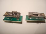
Pero llegó el detalle con el hardware. Los módulos no son aptos para usarse en protoboard.
Entonces realicé unos pequeños adaptadores en PCB, y hasta con máscara antisoldante.
Posteriormente hice el diseñó para el cual tenía pensado usar los módulos.
(Un sistema de control de iluminación con LEDs para una discoteca.)
Tras armar las tarjetas, todo funcionó correctamente al primer encendido.
El sistema funcionó tal cual se requería y se había programado, sin ninguna falla. (Hasta el momento)
Ahora les comparto un proyecto, pero para encender y apagar un simple LED.
Incluye los esquemas y diseños para los PCB, así como también el footprint que usé como adaptador.
(Este footprint les servirá si desean hacer pruebas en protoboard.)
El sistema está funcionando físicamente y no deben tener problemas si realizan todo como está en los esquemas.
Usé dos PIC16F690, ya que con esos realicé mi prototipo.
(Tienen módulo SSP, oscilador interno y la cantidad de pines que yo necesitaba.)
Nota:
Recuerden que si se desea usar otro PIC, éste debe tener módulo SSP, y no olvidar configurar los pines a usar en la librería.
Espero les sea de utilidad.
Cuando yo realicé la prueba de éstos módulos, me funcionó a la primera.
No tuve complicaciones de ningún tipo con el software, con el hardware si tuve, pero lo resolví.
Recuerdo que la primera prueba fue usando Proteus para analizar la comunicación SPI con el debugger.
Noté que existían varias advertencias cuando se hacía el cambio de modo Master/Slave.
Así que en modo de depuración me dediqué a corregir la librería "lib_rf2gh4_10.h"
Esa fue una prueba y corrección en simulador, me quedaba la duda de que funcionaran físicamente.
Pero llegó el detalle con el hardware. Los módulos no son aptos para usarse en protoboard.
Entonces realicé unos pequeños adaptadores en PCB, y hasta con máscara antisoldante.
Posteriormente hice el diseñó para el cual tenía pensado usar los módulos.
(Un sistema de control de iluminación con LEDs para una discoteca.)
Tras armar las tarjetas, todo funcionó correctamente al primer encendido.
El sistema funcionó tal cual se requería y se había programado, sin ninguna falla. (Hasta el momento)
Ahora les comparto un proyecto, pero para encender y apagar un simple LED.
Incluye los esquemas y diseños para los PCB, así como también el footprint que usé como adaptador.
(Este footprint les servirá si desean hacer pruebas en protoboard.)
El sistema está funcionando físicamente y no deben tener problemas si realizan todo como está en los esquemas.
Usé dos PIC16F690, ya que con esos realicé mi prototipo.
(Tienen módulo SSP, oscilador interno y la cantidad de pines que yo necesitaba.)
Nota:
Recuerden que si se desea usar otro PIC, éste debe tener módulo SSP, y no olvidar configurar los pines a usar en la librería.
Espero les sea de utilidad.