Se que hay información acerca del tema pero no he conseguido hacerla funcionar con la información que he encontrado, el driver de ccs es para lcd de 2x16 y a 4mhz, he cambiado los delay_cycles(1) por delay_us(10) y he conseguido que escriba cosas sin sentido. a continuacion añado codigo sacado del foro todopic y modificado lo de los delays.
Preparado para usar el puerto b en vez del d. Este codigo es solo la rutina de ccs pero con modificaciones para ser usada con una linea.
// As defined in the following structure the pin connection is as follows:
// D0 enable
// D1 rs
// D2 rw
// D4 D4
// D5 D5
// D6 D6
// D7 D7
//
// LCD pins D0-D3 are not used and PIC D3 is not used.
// Un-comment the following define to use port B
#define use_portb_lcd TRUE
struct lcd_pin_map { // This structure is overlayed
BOOLEAN enable; // on to an I/O port to gain
BOOLEAN rs; // access to the LCD pins.
BOOLEAN rw; // The bits are allocated from
BOOLEAN unused; // low order up. ENABLE will
int data : 4; // be pin B0.
} lcd;
#if defined(__PCH__)
#if defined use_portb_lcd
#byte lcd = 0xF81 // This puts the entire structure
#else
#byte lcd = 0xF83 // This puts the entire structure
#endif
#else
#if defined use_portb_lcd
#byte lcd = 6 // on to port B (at address 6)
#else
#byte lcd = 8 // on to port D (at address 8)
#endif
#endif
#if defined use_portb_lcd
#define set_tris_lcd(x) set_tris_b(x)
#else
#define set_tris_lcd(x) set_tris_d(x)
#endif
//MODIFICADO POR VITAL... si vas a usar lcd's de 1 linea por 16 declara la varible use_lcd_1x16 en tu programa
// así --> #define use_lcd_1x16 antes del include de este archivo
#if defined use_lcd_1x16
#define lcd_type 0
#else
#define lcd_type 2 // 0=5x7, 1=5x10, 2=2 lines
#define lcd_line_two 0x40 // LCD RAM address for the second line
#endif
BYTE const LCD_INIT_STRING[4] = {0x20 | (lcd_type << 2), 0xc, 1, 6};
// These bytes need to be sent to the LCD
// to start it up.
// The following are used for setting
// the I/O port direction register.
struct lcd_pin_map const LCD_WRITE = {0,0,0,0,0}; // For write mode all pins are out
struct lcd_pin_map const LCD_READ = {0,0,0,0,15}; // For read mode data pins are in
BYTE lcd_read_byte() {
BYTE low,high;
set_tris_lcd(LCD_READ);
lcd.rw = 1;
delay_us(10);
lcd.enable = 1;
delay_us(10);
high = lcd.data;
lcd.enable = 0;
delay_us(10);
lcd.enable = 1;
delay_us(10);
low = lcd.data;
lcd.enable = 0;
set_tris_lcd(LCD_WRITE);
return( (high<<4) | low);
}
void lcd_send_nibble( BYTE n ) {
lcd.data = n;
delay_us(10);
lcd.enable = 1;
delay_us(2);
lcd.enable = 0;
}
void lcd_send_byte( BYTE modo, BYTE n ) {
lcd.rs = 0;
lcd.rw = 1; // MODIFICADO POR VITAL... fallo de la rutina... el protocolo necesita este bit
while ( bit_test(lcd_read_byte(),7) ) ;
lcd.rs = modo; //MODIFICADO POR VITAL... aqui addres lleva a confusión... este bit define el modo comando o texto
delay_us(10);
lcd.rw = 0;
delay_us(10);
lcd.enable = 0;
lcd_send_nibble(n >> 4);
lcd_send_nibble(n & 0xf);
}
void lcd_init() {
BYTE i;
set_tris_lcd(LCD_WRITE);
lcd.rs = 0;
lcd.rw = 0;
lcd.enable = 0;
delay_ms(15);
for(i=1;i<=3;++i) {
lcd_send_nibble(3);
delay_ms(5);
}
lcd_send_nibble(2);
for(i=0;i<=3;++i)
lcd_send_byte(0,LCD_INIT_STRING);
}
void lcd_gotoxy( BYTE x, BYTE y) {
BYTE address;
if(y!=1)
address=0x40;
else
address=0;
address+=x-1;
lcd_send_byte(0,0x80|address);
}
void lcd_putc( char c) {
switch (c) {
case '\f' : lcd_send_byte(0,1);
delay_ms(2);
break;
case '\n' : lcd_gotoxy(1,2); break;
case '\b' : lcd_send_byte(0,0x10); break;
default : lcd_send_byte(1,c); break;
}
}
char lcd_getc( BYTE x, BYTE y) {
char value;
lcd_gotoxy(x,y);
while ( bit_test(lcd_read_byte(),7) ); // wait until busy flag is low
lcd.rs=1;
value = lcd_read_byte();
lcd.rs=0;
return(value);
}
Tambien voy a añadir mi programa principal para para probar el lcd.
#include <16f877a.h>
#fuses HS, NOWDT, NOPROTECT, NOPUT, NOBROWNOUT, NOLVP, NOCPD, NODEBUG, NOWRT
#use delay (clock=20000000)
#use standard_io(C)
#use standard_io(B)
#use standard_io(E)
#use standard_io(D)
#define use_portb_lcd
#define use_lcd_1x16
#INCLUDE "lcd20mh.c"
void main()
{
set_tris_d(0x00);
set_tris_c(0x00);
output_c(0x00);
delay_ms(200);
lcd_init(); // Inicializar LCD
delay_ms(200);
do{
output_high(PIN_D0);
lcd_putc('P');
lcd_putc('u');
lcd_putc('l');
lcd_putc('s');
lcd_putc('a');
lcd_putc(' ');
lcd_putc('u');
lcd_putc('n');
lcd_putc('a');
delay_ms(500);
lcd_putc('\f');
delay_ms(500);
}while(1);
}
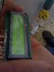
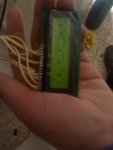
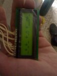
Lo que me sale por pantalla es: flecha o flecha o _ flecha _ o
Con lo que no entiendo nada para sacar estos caracteres la parte baja debe estar todo a 1 y no es asi, esta al aire.
Preparado para usar el puerto b en vez del d. Este codigo es solo la rutina de ccs pero con modificaciones para ser usada con una linea.
// As defined in the following structure the pin connection is as follows:
// D0 enable
// D1 rs
// D2 rw
// D4 D4
// D5 D5
// D6 D6
// D7 D7
//
// LCD pins D0-D3 are not used and PIC D3 is not used.
// Un-comment the following define to use port B
#define use_portb_lcd TRUE
struct lcd_pin_map { // This structure is overlayed
BOOLEAN enable; // on to an I/O port to gain
BOOLEAN rs; // access to the LCD pins.
BOOLEAN rw; // The bits are allocated from
BOOLEAN unused; // low order up. ENABLE will
int data : 4; // be pin B0.
} lcd;
#if defined(__PCH__)
#if defined use_portb_lcd
#byte lcd = 0xF81 // This puts the entire structure
#else
#byte lcd = 0xF83 // This puts the entire structure
#endif
#else
#if defined use_portb_lcd
#byte lcd = 6 // on to port B (at address 6)
#else
#byte lcd = 8 // on to port D (at address 8)
#endif
#endif
#if defined use_portb_lcd
#define set_tris_lcd(x) set_tris_b(x)
#else
#define set_tris_lcd(x) set_tris_d(x)
#endif
//MODIFICADO POR VITAL... si vas a usar lcd's de 1 linea por 16 declara la varible use_lcd_1x16 en tu programa
// así --> #define use_lcd_1x16 antes del include de este archivo
#if defined use_lcd_1x16
#define lcd_type 0
#else
#define lcd_type 2 // 0=5x7, 1=5x10, 2=2 lines
#define lcd_line_two 0x40 // LCD RAM address for the second line
#endif
BYTE const LCD_INIT_STRING[4] = {0x20 | (lcd_type << 2), 0xc, 1, 6};
// These bytes need to be sent to the LCD
// to start it up.
// The following are used for setting
// the I/O port direction register.
struct lcd_pin_map const LCD_WRITE = {0,0,0,0,0}; // For write mode all pins are out
struct lcd_pin_map const LCD_READ = {0,0,0,0,15}; // For read mode data pins are in
BYTE lcd_read_byte() {
BYTE low,high;
set_tris_lcd(LCD_READ);
lcd.rw = 1;
delay_us(10);
lcd.enable = 1;
delay_us(10);
high = lcd.data;
lcd.enable = 0;
delay_us(10);
lcd.enable = 1;
delay_us(10);
low = lcd.data;
lcd.enable = 0;
set_tris_lcd(LCD_WRITE);
return( (high<<4) | low);
}
void lcd_send_nibble( BYTE n ) {
lcd.data = n;
delay_us(10);
lcd.enable = 1;
delay_us(2);
lcd.enable = 0;
}
void lcd_send_byte( BYTE modo, BYTE n ) {
lcd.rs = 0;
lcd.rw = 1; // MODIFICADO POR VITAL... fallo de la rutina... el protocolo necesita este bit
while ( bit_test(lcd_read_byte(),7) ) ;
lcd.rs = modo; //MODIFICADO POR VITAL... aqui addres lleva a confusión... este bit define el modo comando o texto
delay_us(10);
lcd.rw = 0;
delay_us(10);
lcd.enable = 0;
lcd_send_nibble(n >> 4);
lcd_send_nibble(n & 0xf);
}
void lcd_init() {
BYTE i;
set_tris_lcd(LCD_WRITE);
lcd.rs = 0;
lcd.rw = 0;
lcd.enable = 0;
delay_ms(15);
for(i=1;i<=3;++i) {
lcd_send_nibble(3);
delay_ms(5);
}
lcd_send_nibble(2);
for(i=0;i<=3;++i)
lcd_send_byte(0,LCD_INIT_STRING);
}
void lcd_gotoxy( BYTE x, BYTE y) {
BYTE address;
if(y!=1)
address=0x40;
else
address=0;
address+=x-1;
lcd_send_byte(0,0x80|address);
}
void lcd_putc( char c) {
switch (c) {
case '\f' : lcd_send_byte(0,1);
delay_ms(2);
break;
case '\n' : lcd_gotoxy(1,2); break;
case '\b' : lcd_send_byte(0,0x10); break;
default : lcd_send_byte(1,c); break;
}
}
char lcd_getc( BYTE x, BYTE y) {
char value;
lcd_gotoxy(x,y);
while ( bit_test(lcd_read_byte(),7) ); // wait until busy flag is low
lcd.rs=1;
value = lcd_read_byte();
lcd.rs=0;
return(value);
}
Tambien voy a añadir mi programa principal para para probar el lcd.
#include <16f877a.h>
#fuses HS, NOWDT, NOPROTECT, NOPUT, NOBROWNOUT, NOLVP, NOCPD, NODEBUG, NOWRT
#use delay (clock=20000000)
#use standard_io(C)
#use standard_io(B)
#use standard_io(E)
#use standard_io(D)
#define use_portb_lcd
#define use_lcd_1x16
#INCLUDE "lcd20mh.c"
void main()
{
set_tris_d(0x00);
set_tris_c(0x00);
output_c(0x00);
delay_ms(200);
lcd_init(); // Inicializar LCD
delay_ms(200);
do{
output_high(PIN_D0);
lcd_putc('P');
lcd_putc('u');
lcd_putc('l');
lcd_putc('s');
lcd_putc('a');
lcd_putc(' ');
lcd_putc('u');
lcd_putc('n');
lcd_putc('a');
delay_ms(500);
lcd_putc('\f');
delay_ms(500);
}while(1);
}
Lo que me sale por pantalla es: flecha o flecha o _ flecha _ o
Con lo que no entiendo nada para sacar estos caracteres la parte baja debe estar todo a 1 y no es asi, esta al aire.