Encendido por aplauso:
This circuit has been designed to respond only to two hand claps which occur in (relatively) quick succession, and to ignore one hand clap or even continuous clapping, as well as most other sounds which normally have a lower frequency contents than a hand clap. Even so, the system is not foolproof but is should be adequate for simple domestic applications such as switching lights on and off.
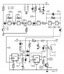
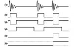
The circuit diagram and the accompanying timing diagram will be discussed briefly to explain the basic operation of the circuit. The sound picked up by the electret microphone is first amplificadorfied to a level suitable for further processing. This is done with two inverters from a 4049 IC, which is normally listed as a ‘hex inverter’ package. By connecting high value feedback resistors between the input and output of each inverter, and coupling the inverters with a capacitor (C3), a primitive but otherwise perfectly adequate analogue amplificadorfier is created. The value of capacitor C2 at the amplificadorfier input is such that only higher frequency sounds are amplificadorfied. The amplificadorfier output
signal is ‘squared’ before being used to charge C4 via D1. The final two inverters from the 4049 package, IC1e and IC1f, are configured to act as a Schmitt trigger.
The first inverter of this pair produces a negative pulse each time a sound of sufficient amplitude is picked up by the microphone. The duration of this pulse is determined by that of the sound and the values of C4-R6 which are chosen to ensure that the output will only go high when the sound ceases. The final inverter produces a corresponding positive pulse.
The rising edge of the Schmitt trigger output signal is differentiated by C6-R9 producing a positive going pulse when the sound ceases. This triggers monostable IC2a built around one half of a 4013 dual D flip-flop. If a second pulse appears on D3 after the first one has ceased, while the output of the monostable is still high, the clock input of toggle flip-flop IC2b will go high causing the Q output to go high and T1 to be turned on. Consequently relay Re1 is energized and the
load is switched on and will remain on until a valid clap command is received (toggle function).
LED D1 is connected to the Q output of IC2a and will indicate the time slot available for the two successive claps. The circuit is best powered from a mains adaptor set to achieve about 12 V DC output voltage when loaded with 40 mA plus the relay coil current.
R1: 10k
R2: 100k
R3: 1M
R4: 22k
R5: 330k
R6: 4,7M
R7: 47k
R8: 470k
R9: 10k
R10:1k
R11:470k
R12:10k
R13:4k7
R14:150
C1: 100uF 25V
C2: 1n
C3: 100n
C4: 100n
C5: 1n
C6: 1n
C7: 2,2uF 16V
C8: 470uF 16V
D1: 1N4148
D4: 1N4148
D5: 8V2
D6: 1N4148
T1: BC547B