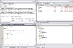
Hola a todos, ya supe que no se puede simular el funcionamiento del DAC con el MPLAB SIM, entonces lo quice depurar por medio de mi programador (PICkit3), pero tampoco puedo observar su funcionamiento.
Intento cargarle un valor al DAC1RDAT con la variable i pero no se carga, tampoco se activa la bandera de interrupción del DAC (IFS4bits.DAC1RIF), y no hay cambios en el bit de estado DAC1STATbits.RFULL. Por favor si alguién ya ha manejado el DAC en un dsPIC33F le agradezco inmensamente que me regale unos segundos y revise el código para observar qué puede estar mal.
Nota: Por ahora no tengo osciloscopio para observar una señal.
Intento cargarle un valor al DAC1RDAT con la variable i pero no se carga, tampoco se activa la bandera de interrupción del DAC (IFS4bits.DAC1RIF), y no hay cambios en el bit de estado DAC1STATbits.RFULL. Por favor si alguién ya ha manejado el DAC en un dsPIC33F le agradezco inmensamente que me regale unos segundos y revise el código para observar qué puede estar mal.
Código:
#include "p33FJ64GP802.h"

	//CONFIGURATION BITS
_FBS( BWRP_WRPROTECT_OFF & BSS_NO_FLASH & RBS_NO_RAM )
_FSS( RSS_NO_RAM & SSS_NO_FLASH & SWRP_WRPROTECT_OFF )
_FGS( GSS_OFF & GCP_OFF & GWRP_OFF )
_FOSCSEL(FNOSC_PRIPLL & IESO_ON);								// Primary oscillator (XT, HS, EC) w/ PLL, Two-speed Oscillator Startup : Enabled
_FOSC(FCKSM_CSDCMD & IOL1WAY_OFF & OSCIOFNC_OFF & POSCMD_XT );	// Clock switching and clock monitor:Disabled & Single configuration for remappable I/O:Disabled & OSC2 is clock O/P & XT oscillator
_FWDT( FWDTEN_OFF & WINDIS_OFF )
_FPOR( ALTI2C_OFF & FPWRT_PWR128 )
_FICD( BKBUG_ON & COE_ON & JTAGEN_OFF & ICS_PGD1 )

unsigned int i = 0;

int main (void)
{
	// Oscillator Special Function Control Registers
	// Configure Oscillator to operate the device at 40MIPS
	// Fosc= Fin*M/(N1*N2), Fcy=Fosc/2 (XT=10MHz)

PLLFBD = 30; 				//PLL Feedback Divisor bits (also denoted as "M", PLL multiplier) 30 = 32

CLKDIVbits.PLLPRE = 0; 		//PLL Phase Detector Input Divider bits (also denoted as "N1", PLL prescaler) 0 = 2
CLKDIVbits.PLLPOST = 0; 	//PLL VCO Output Divider Select bits (also denoted as "N2", PLL postscaler) 0 = 2
//CLKDIVbits.FRCDIV = 0;	//Internal Fast RC Oscillator Postscaler bits
CLKDIVbits.DOZEN = 0;		//DOZE Mode Enable bit 0 = Processor clock/peripheral clock ratio forced to 1:1
//CLKDIVbits.DOZE = 0;		//Processor Clock Reduction Select bits = FCY/1
CLKDIVbits.ROI = 0;			//Recover on Interrupt bit 0 = Interrupts have no effect on the DOZEN bit

//OSCTUNbits.TUN = 0;		//FRC Oscillator Tuning bits = Center frequency (7.37 MHz nominal)

ACLKCONbits.SELACLK = 0;	//0 = FRC with PLL provides the source clock for Auxiliary Clock Divider
ACLKCONbits.AOSCMD = 0;		//00 = Auxiliary Oscillator Disabled
ACLKCONbits.APSTSCLR = 7;	//Auxiliary Clock Output Divider 7 = /1
//ACLKCONbits.ASRCSEL = 0;	//Select Reference Clock Source for Auxiliary Clock 0 = AOSCCLK


DAC1STATbits.ROEN = 1;		//Right Channel DAC output enable 1 = enabled
//DAC1STATBITS.LOEN=;		//Left Channel DAC output enable

DAC1STATbits.RITYPE = 0;	//Right Channel Type of Interrupt 0 = Interrupt if FIFO is NOT FULL.
//DAC1STATBITS.LITYPE=;		//Left Channel Type of Interrupt

DAC1STATbits.RMVOEN = 0;	//Right Channel Midpoint DAC output voltage enable 0 = disabled
//DAC1STATBITS.LMVOEN=;		//Left Channel Midpoint DAC output voltage enable

DAC1CONbits.DACFDIV = 3;	//DAC Clock Divider 3 = /4
DAC1CONbits.FORM = 0;		//Data Format Select bit 0 = Unsigned integer
//DAC1CONbits.AMPON = 0;		//0 = Analog Output Amplifier is disabled during Sleep Mode/Stop-in Idle mode
//DAC1CONbits.DACSIDL = 0;	//Stop in Ideal Mode bit 0 = Continue module operation in Idle mode.

DAC1DFLT = 65535;			//DAC DEFAULT DATA REGISTER

DAC1CONbits.DACEN = 1;		//DAC1 Enable bit 1 = Enables module

IFS4bits.DAC1RIF = 0; 		// Clear Right Channel Interrupt Flag
//IFS4bits.DAC1LIF = 0; 	// Clear Left Channel Interrupt Flag */

IPC19bits.DAC1RIP = 7;		//7 = Interrupt is priority 7 (highest priority interrupt)
//IPC19bits.DAC1LIP = 0;

IEC4bits.DAC1RIE = 1; 		// Right Channel Interrupt Enabled
//IEC4bits.DAC1LIE = 1; 	// Left Channel Interrupt Enabled

	// PLLCLK/SELACLK/DACFDIV = DACCLK
	// 80 MHz/1/4 = 20 MHz
	// Fs = 78.125 KHz

while (1)
{
	if ((DAC1STATbits.RFULL == 0 ) && (i <= 65535))
	{
	DAC1RDAT = i;
		if (i == 65535)
		{
		i = 0;
		}
	i = i + 1;
	}
}
}

void __attribute__((interrupt, no_auto_psv)) _DAC1RInterrupt(void)
{
IFS4bits.DAC1RIF = 0;  		// Clear Right Channel Interrupt Flag
}
Nota: Por ahora no tengo osciloscopio para observar una señal.