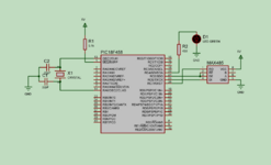
Hola a todos, quería saber si pueden ayudarme con esta situación. Resulta que tengo estoy tratando de establecer un comunicación rs485 entre la pc y un microcontrolador pic. Así como está en el diagrama. A y B va conectados a la computadora. De momento solo busco lo siguiente:
1. Enviar un carácter de la pc al microcontrolador.
2. El microcontrolador lee el carácter.
3. El microcontrolador retorna ese carácter a la PC.
4. El microcontrolador se mantiene a la espera de otro carácter.
Sucede que haciendo pruebas ocurre lo siguiente:
1. Envío 0x97 de la PC al microcontrolador.
2. El microcontrolador lee 0x97.
3. El microcontrolador retorna 0x97 a la pc.
4. El microcontrolador retorna 0x00 a la pc.
y repite el paso 4 indefinidamente.
acá les dejo el código que estoy implementando.
DIAGRAMA DEL CIRCUITO

De que manera puedo corregirlo? Agradecería cualquier sugerencia.
1. Enviar un carácter de la pc al microcontrolador.
2. El microcontrolador lee el carácter.
3. El microcontrolador retorna ese carácter a la PC.
4. El microcontrolador se mantiene a la espera de otro carácter.
Sucede que haciendo pruebas ocurre lo siguiente:
1. Envío 0x97 de la PC al microcontrolador.
2. El microcontrolador lee 0x97.
3. El microcontrolador retorna 0x97 a la pc.
4. El microcontrolador retorna 0x00 a la pc.
y repite el paso 4 indefinidamente.
acá les dejo el código que estoy implementando.
C:
// CONFIG1H
#pragma config OSC = HS         // Oscillator Selection bits (HS oscillator)
#pragma config OSCS = OFF       // Oscillator System Clock Switch Enable bit (Oscillator system clock switch option is disabled (main oscillator is source))

// CONFIG2L
#pragma config PWRT = OFF       // Power-up Timer Enable bit (PWRT disabled)
#pragma config BOR = ON         // Brown-out Reset Enable bit (Brown-out Reset enabled)
#pragma config BORV = 25        // Brown-out Reset Voltage bits (VBOR set to 2.5V)

// CONFIG2H
#pragma config WDT = OFF        // Watchdog Timer Enable bit (WDT disabled (control is placed on the SWDTEN bit))
#pragma config WDTPS = 128      // Watchdog Timer Postscale Select bits (1:128)

// CONFIG4L
#pragma config STVR = ON        // Stack Full/Underflow Reset Enable bit (Stack Full/Underflow will cause Reset)
#pragma config LVP = OFF         // Low-Voltage ICSP Enable bit (Low-Voltage ICSP enabled)

// CONFIG5L
#pragma config CP0 = OFF        // Code Protection bit (Block 0 (000200-001FFFh) not code protected)
#pragma config CP1 = OFF        // Code Protection bit (Block 1 (002000-003FFFh) not code protected)
#pragma config CP2 = OFF        // Code Protection bit (Block 2 (004000-005FFFh) not code protected)
#pragma config CP3 = OFF        // Code Protection bit (Block 3 (006000-007FFFh) not code protected)

// CONFIG5H
#pragma config CPB = OFF        // Boot Block Code Protection bit (Boot Block (000000-0001FFh) not code protected)
#pragma config CPD = OFF        // Data EEPROM Code Protection bit (Data EEPROM not code protected)

// CONFIG6L
#pragma config WRT0 = OFF       // Write Protection bit (Block 0 (000200-001FFFh) not write protected)
#pragma config WRT1 = OFF       // Write Protection bit (Block 1 (002000-003FFFh) not write protected)
#pragma config WRT2 = OFF       // Write Protection bit (Block 2 (004000-005FFFh) not write protected)
#pragma config WRT3 = OFF       // Write Protection bit (Block 3 (006000-007FFFh) not write protected)

// CONFIG6H
#pragma config WRTC = OFF       // Configuration Register Write Protection bit (Configuration registers (300000-3000FFh) not write protected)
#pragma config WRTB = OFF       // Boot Block Write Protection bit (Boot Block (000000-0001FFh) not write protected)
#pragma config WRTD = OFF       // Data EEPROM Write Protection bit (Data EEPROM not write protected)

// CONFIG7L
#pragma config EBTR0 = OFF      // Table Read Protection bit (Block 0 (000200-001FFFh) not protected from Table Reads executed in other blocks)
#pragma config EBTR1 = OFF      // Table Read Protection bit (Block 1 (002000-003FFFh) not protected from Table Reads executed in other blocks)
#pragma config EBTR2 = OFF      // Table Read Protection bit (Block 2 (004000-005FFFh) not protected from Table Reads executed in other blocks)
#pragma config EBTR3 = OFF      // Table Read Protection bit (Block 3 (006000-007FFFh) not protected from Table Reads executed in other blocks)

// CONFIG7H
#pragma config EBTRB = OFF      // Boot Block Table Read Protection bit (Boot Block (000000-0001FFh) not protected from Table Reads executed in other blocks)

#define _XTAL_FREQ 20000000

#include <xc.h>

void main(void) {
    char dato;
    TRISC=0;
    TRISCbits.RC7 = 1;
    PORTC=0;
    /*
    INTCONbits.PEIE=1;
    INTCONbits.GIE=0;
    */

    //UART INIT
    TXSTAbits.BRGH = 1;
    SPBRG = 129;

    TXSTAbits.SYNC = 0;
    RCSTAbits.SPEN = 1;

    TXSTAbits.TX9 = 0;
    RCSTAbits.RX9 = 0;

    TXSTAbits.TXEN = 1;
    RCSTAbits.CREN = 1;

    PIE1bits.RCIE=1;

    while(1){

        if (PIR1bits.RCIF==1){
            // leer el dato de entrada
            dato = RCREG;
            if (RCSTAbits.OERR){
                RCSTA1bits.CREN=0;
                RCSTAbits.CREN=1;
            }

            //Habilitar MAX485 para transmision
            PORTCbits.RC5 = 1;
            __delay_ms(100);

            //Enviar dato recibido
            TXREG = dato;
            while(TXSTAbits.TRMT == 0);

            //Habilitar max485 para recepcion
            PORTCbits.RC5 = 0;

        }
    }
    return;
}
DIAGRAMA DEL CIRCUITO

De que manera puedo corregirlo? Agradecería cualquier sugerencia.


