Modificar librería para LCD 20x4

Hola. ¿Alguien podría ayudarme a modificar la librería 20x4 (LCD420) de CCS?
Necesito que funcione para usarla en el puerto D, ya que por defecto viene en el puerto B.
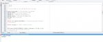
Aquí dejo el driver que tiene CCS:
Código:
////////////////////////////////////////////////////////////////////////////
////                             LCD420.C                               ////
////            Driver for common 4x20 LCD modules                      ////
////                                                                    ////
////  lcd_init()   Must be called before any other function.            ////
////                                                                    ////
////  lcd_putc(c)  Will display c on the next position of the LCD.      ////
////                     The following have special meaning:            ////
////                      \f  Clear display                             ////
////                      \n  Go to start of second line                ////
////                      \b  Move back one position                    ////
////                                                                    ////
////  lcd_gotoxy(x,y) Set write position on LCD (upper left is 1,1)     ////
////                                                                    ////
////  lcd_getc(x,y)   Returns character at position x,y on LCD          ////
////                                                                    ////
////////////////////////////////////////////////////////////////////////////
////        (C) Copyright 1996,1997 Custom Computer Services            ////
//// This source code may only be used by licensed users of the CCS C   ////
//// compiler.  This source code may only be distributed to other       ////
//// licensed users of the CCS C compiler.  No other use, reproduction  ////
//// or distribution is permitted without written permission.           ////
//// Derivative programs created using this software in object code     ////
//// form are not restricted in any way.                                ////
////////////////////////////////////////////////////////////////////////////

// As defined in the following structure the pin connection is as follows:
//     B0  enable
//     B1  rs
//     B2  rw
//     B4  D4
//     B5  D5
//     B6  D6
//     B7  D7
//
//   LCD pins D0-D3 are not used and PIC B3 is not used.

struct lcd_pin_map {                 // This structure is overlayed
           BOOLEAN enable;           // on to an I/O port to gain
           BOOLEAN rs;               // access to the LCD pins.
           BOOLEAN rw;               // The bits are allocated from
           BOOLEAN unused;           // low order up.  ENABLE will
           int     data : 4;         // be pin B0.
        } lcd;

#locate lcd = getenv("SFR:PORTB")                        // This puts the entire structure
                                     // on to port B 

#define lcd_type 2           // 0=5x7, 1=5x10, 2=2 lines


BYTE const LCD_INIT_STRING[4] = {0x20 | (lcd_type << 2), 0xc, 1, 6};
                             // These bytes need to be sent to the LCD
                             // to start it up.


                             // The following are used for setting
                             // the I/O port direction register.

struct lcd_pin_map const LCD_WRITE = {0,0,0,0,0}; // For write mode all pins are out
struct lcd_pin_map const LCD_READ = {0,0,0,0,15}; // For read mode data pins are in


BYTE lcdline;

BYTE lcd_read_byte() {
      BYTE low,high;

      set_tris_b(LCD_READ);
      lcd.rw = 1;
      delay_cycles(1);
      lcd.enable = 1;
      delay_cycles(1);
      high = lcd.data;
      lcd.enable = 0;
      delay_cycles(1);
      lcd.enable = 1;
      delay_us(1);
      low = lcd.data;
      lcd.enable = 0;
      set_tris_b(LCD_WRITE);
      return( (high<<4) | low);
}


void lcd_send_nibble( BYTE n ) {
      lcd.data = n;
      delay_cycles(1);
      lcd.enable = 1;
      delay_us(2);
      lcd.enable = 0;
}


void lcd_send_byte( BYTE address, BYTE n ) {

      lcd.rs = 0;
      while ( bit_test(lcd_read_byte(),7) ) ;
      lcd.rs = address;
      delay_cycles(1);
      lcd.rw = 0;
      delay_cycles(1);
      lcd.enable = 0;
      lcd_send_nibble(n >> 4);
      lcd_send_nibble(n & 0xf);
}


void lcd_init() {
    BYTE i;

    set_tris_b(LCD_WRITE);
    lcd.rs = 0;
    lcd.rw = 0;
    lcd.enable = 0;
    delay_ms(15);
    for(i=1;i<=3;++i) {
       lcd_send_nibble(3);
       delay_ms(5);
    }
    lcd_send_nibble(2);
    for(i=0;i<=3;++i)
       lcd_send_byte(0, LCD_INIT_STRING[i]);
}


void lcd_gotoxy( BYTE x, BYTE y) {
   BYTE address;

   switch(y) {
     case 1 : address=0x80;break;
     case 2 : address=0xc0;break;
     case 3 : address=0x94;break;
     case 4 : address=0xd4;break;
   }
   address+=x-1;
   lcd_send_byte(0,address);
}

void lcd_putc( char c) {
   switch (c) {
     case '\f'   : lcd_send_byte(0,1);
                   lcdline=1;
                   delay_ms(2);
                                           break;
     case '\n'   : lcd_gotoxy(1,++lcdline);        break;
     case '\b'   : lcd_send_byte(0,0x10);  break;
     default     : lcd_send_byte(1,c);     break;
   }
}

char lcd_getc( BYTE x, BYTE y) {
   char value;

    lcd_gotoxy(x,y);
    lcd.rs=1;
    value = lcd_read_byte();
    lcd.rs=0;
    return(value);
}

Su ayuda me será muy grata
 
Última edición por un moderador:
Cambia la línea

#locate lcd = getenv("SFR:PORTB")

por

#locate lcd = getenv("SFR:pORTD")
 
Hola. ¿Alguien podría ayudarme a modificar la librería 20x4 (LCD420) de CCS?
Necesito que funcione para usarla en el puerto D, ya que por defecto viene en el puerto B.
Su ayuda me será muy grata
Aparte de lo que te mencionó @JoaquinFerrero, también tienes que modificar las instrucciones TRIS que hacen referencia al puerto B.
O sea, estas instrucciones set_tris_b(X); por ---> set_tris_d(X);

Mira este post, aquí ya está modificada para trabajar por el puerto D. Problemas con Display LCD en CCS

Suerte.
 
Ya arreglé el problema AleSergi. Supongo que tenías razón. El problema que tenía es que compilaba la librería nueva y me daba error, me pedía algo así como agregar un #device, entonces lo que hice fue agregar una librería que me proporcionó D@rkbytes donde ya estaba modificada para trabajar en el puerto D. Gracias


Muchas gracias D@rkbytes me funciono bien imprimir con putc, el unico problema que tengo es intentar imprimir con printf()... Pero gracias de verdad, funciona bien con el puerto D
 
Última edición:
hola miglo!
me refiero que cambie el código lcd420.c con las recomendaciones del foro,
se especifica como hacer cambios para e,rw,rs y el puerto de salida
struct lcd_pin_map { // This structure is overlayed
BOOLEAN enable; // on to an I/O port to gain
BOOLEAN rs; // access to the LCD pins.
BOOLEAN rw; // The bits are allocated from
BOOLEAN unused; // low order up. ENABLE will
int data : 4; // be pin B0.
} lcd;

#locate lcd = getenv("SFR:pORTB")
pero necesitaba cambiar la salida de D4,D5,D6,D7 que sale en este caso B4,B5,B6,B7

ya encontre una solucion con el flex_cd420.c
 
Bueno me alegro que lo hayas conseguido, pero mas o menos creo que JoaquinFerrero ya te explico como cambiar el puerto B por el D, #locate lcd = getenv("SFR:pORTB") por #locate lcd = getenv("SFR:pORTD").
Luego D@rbytes recalco la matizacion de cambiar tambien las instrucciones de set_tris_b(X); por set_tris_d(X);.

Posdata esto mismo es lo que suelo hacer yo cuando hago mis pruebas.

Otra posdata, yo tambien utilizaba la libreria flex_lcd420 y deje de usarla por que cuando simulaba en proteus se me cargaba mucho el programa.
 
16f.jpghola miglo!
como le comentaba anteriormente hice los cambios como indicaron en el foro
he querido cambiar los pines de salida del pic para D4,D5,D6,D7 subo una imagen para ser mas claro
gracias por la atencion
 
Ajammm ya creo entender lo que quieres decir, fijate, lo que te pongo acontinuacio pertenece a la libreria que yo uso "lcd420", si te fijas hay esta la rutina de las direcciones.

Código:
void lcd_gotoxy( BYTE x, BYTE y) {
   BYTE address;

   switch(y) {
    case 1 : address=0x80;break;
    
    case 2 : address=0xc0;break;
    
    case 3 : address=0x94;break;
     
     case 4 : address=0xd4;break;
   }

Donde pone case 3: pon la direccion del case 4: y viceversa donde pone case 4: pon la direccion del case 3:, creo que es esto lo que buscas.

Se me olvidaba, esto es para el puerto B que yo uso,en tu caso veo que usas el puerto A.
 
Última edición:
Atrás
Arriba