

Hola a todos, después de pasar varias tardes esta semana, y unas últimas horas hoy intentando descubrir el problema sin éxito, recurro a vosotros, a ver si alguno puede indicarme que estoy haciendo mal...
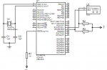
El circuito como veis (adjuntado) es muy sencillito... PIC, Xtal, y el sensor, con sus correspondientes resistencias de desacoplo...
El código, en HI-TECH (MPLAB):
Las funciones, son estándar, copiadas y pegadas a las dadas por Philips. No las pongo, pero si queréis las incluyo... El caso es que al simular, me recorre correctamente todo el código, pero siempre me guarda en las variables el valor FF. Es decir, al final siempre me queda a=FF, b=FF, c=FF y d=FF, cuando debería guardar el valor de la temperatura dada por el sensor.
Indicar que el código está realizado para un sensor digipicco de temperatura y humedad, de ahí que tome 8 bytes, cuando en la simulación, solo entregará 4, ya que es un sensor TC74 de temperatura. Pero ahí no creo que esté el problema, ya que depurando, el valor de la variable 'a' ya me la carga incorrectamente.
No sé que puede pasar, si es un problema del esquemático en Proteus o qué.... ¿alguna idea?
Gracias!
El circuito como veis (adjuntado) es muy sencillito... PIC, Xtal, y el sensor, con sus correspondientes resistencias de desacoplo...
El código, en HI-TECH (MPLAB):
Código:
#include <pic.h> //Standard Hi-Tec C header file this includes the definition for the generic functions and variables i.e TRISC, PORTC, TXREG
#include "i2c.h" //Defines the I2C functions, this came with the HI-Tec C

/*Setting the config register.
Watchdog Timer Disable
Using Hi Speed Xtal
Low voltage program mode disable
*/
__CONFIG (WDTDIS & HS & LVPDIS);

void putrsUSART(const char *data); //Function prototype, this defines the functions other than the main() function

void main()
{
 		INTCON= 0;     //Disable Interrupts
 		SPBRG = 129;  //Set the baudrate for 9600 @ 20 MHz (0x81)
 		TXSTA = 0x24; //Set the serial port parameters
 		RCSTA = 0x90; //Set the serial port parameters
 		PORTC = 0;    //Clear PORTC pins
 		TRISC = 0x80; //Set the PORTC pin directions i.e Tx and Rx

 int a, b, c, d; //Variables holds I2C Data
 char td[4];     //Char Array to store I2C Data, this will be sent to the Serial port

/*
Continuosly monitor the I2C bus and read the humidity and temperature data
And send the data to the Serial Port
*/
	 while(1)
 	{
  			i2c_Start();               //Initiate the I2C bus
 			i2c_SendByte(0xA5);     //Send the Address of the Digipcco sensor to the I2C bus
  			i2c_ReadAcknowledge();     //Read the ACK from the sensor
  			__delay_us(2);         //wait for some time

  			a=i2c_ReadByte();          //Now the sensor sends the first Byte so we gonna read it and save it on the variable a
   			i2c_SendAcknowledge(1);    //Send an ACK to the sensor so it can send the second Byte, we sends the value (1) so the sensor knows we waiting for more data
  			__delay_us(2);

			b=i2c_ReadByte();          //Second byte (MSB of the Humidity)
  			i2c_SendAcknowledge(1);
  			__delay_us(2);

  			c=i2c_ReadByte();          //Third byte (LSB of the Temperature)
  			i2c_SendAcknowledge(1);
  			__delay_us(2);

  			d=i2c_ReadByte();          //Fourth byte (MSB of the Temperature)
  			i2c_SendAcknowledge(0);    //Sending (0) telling the sensor that we done
  			__delay_us(2);

  			i2c_Stop();                //Stop the sensor sending data
  			__delay_us(2);

  			td[0]=a;                   //Filling the I2C Data into a Char Array
  			td[1]=b;
  			td[2]=c;
  			td[3]=d;

			putrsUSART(td);            //Send the 4 Bytes Char Array to the serial port

			for(int t=0;t<4;t++)       //Cleaning the data array, so that we can avoid repeating the same data
 			{
   					__delay_us(20000);
   					td[t]=0;
  			}
 	}
}

void putrsUSART(const char *data)  //Function we use to send the data to the Serial port, const char *data is the Char array
{
 	do  //Check the Char Array until it finishes data
 	{
  		while(!(TXSTA & 0x02)); //Check the TXREG is empty
   		TXREG = *data;          //Send the Byte to the TXREG
 	}
 	while( *data++ );//Check the Char Array until it finishes data
}
Las funciones, son estándar, copiadas y pegadas a las dadas por Philips. No las pongo, pero si queréis las incluyo... El caso es que al simular, me recorre correctamente todo el código, pero siempre me guarda en las variables el valor FF. Es decir, al final siempre me queda a=FF, b=FF, c=FF y d=FF, cuando debería guardar el valor de la temperatura dada por el sensor.
Indicar que el código está realizado para un sensor digipicco de temperatura y humedad, de ahí que tome 8 bytes, cuando en la simulación, solo entregará 4, ya que es un sensor TC74 de temperatura. Pero ahí no creo que esté el problema, ya que depurando, el valor de la variable 'a' ya me la carga incorrectamente.
No sé que puede pasar, si es un problema del esquemático en Proteus o qué.... ¿alguna idea?
Gracias!
")