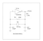
I made the oscillator on my breadboard, but the 1M ohm Rf resistor is mandatory to use, otherwise the circuit doesn't work.
I used 22pf caps (which I have) and I get 4MHZ output from 4011 IC.
First of all, im glad you're trying.
you said "caps" not "cap". You have to replace the inverter output cap to ground entirely with the sensor, otherwise the cap will stabilize the frequency. (our goal is to unstabilize it)
But my sensor-making experiment has failed.
I used 4cm height, 1.2 meters length aluminium strips with 1mm plastic band as dielectric. And I connected it using short crocodile cables to the oscillator circuit.
Try using a 4mm dielectric. Mine is assembled with this:
http://www.papeleradelmar.com.ar/ap.../product/1d77fbc1b0ce1bcbbfa5db205840e7da.jpg
I dont know the english word for that material (perhaps Styrofoam??)
When I connect it to the circuit, the output became 3.966MHZ, when I disconnect it the output is 4MHZ
Also tried 2 parallel 22pF (44pF) caps on one side of XT.
I didn't see any frequency changing on the output when I'm near to the sensor or not. But when I touch the sensor, it is 800Hz
Do you have a cap-meter? the input side cap should be with capacitance as close as possible with your sensor. Also the crystal to use is related with those values.
For instance, with a 20mhz crystal should be about 10pF, with a 4Mhz one, 47pF (dont know the formula... those are values used on the pic crystal)
It's normal the fact that when you touch the sensor the frequency changes a lot.
I think maybe the problem is in the diameter of the dielectric, or in the type of the dielectric I use.
What do you think about this?
What is the (base) frequency when your sensor is connected?
I'd look that way, try different dielectric sizes. My base frequency is about 3.9mhz (not exactly but it's been a while since i tried last time) with a 4mhz crystal. Also tried 20mhz crystal to have more pulses to count on a 100ms sample but it was more stable at 4mhz.
Also, check datasheet for the gate you're using, perhaps doesnt work on those frequencies. (40106 isnt supposed to work at 4mhz but it works!... weird)
EDIT:
I also now tried to remove the crystal from the working circuit and saw that my multimeter measures 4.2MHZ. I've put there 12MHZ crystal and the output is 4.6MHZ. Put there 3.7..KHZ crystal and the output is 3.5MHZ. Put there a 26MHZ crystal, the output is 4.8MHZ.
Is this normal?
I'm using nand gate of 4011 as NOT gate and metal crystals.
Best regards.
This is normal based on my experiments. In order to get the frequency of the crystal, the caps should be of certain values. I wish i knew the formula for that.
What happens when you remove the crystal is that the gate still oscillates, this is normal. The crystal is there to only stabilize the frequency. (as far as i know)
My practical formula is: As crystal is bigger, caps should be smaller. Try to measure your "sensor" cap. If it's around 10pF use 20mhz, 47pF, use 4mhz and so on.
Try power it with 9-12v instead of 5v (you'll have to adapt the output signal to a pic later)
Also, when you post messages, please paste a spanish google translation under it. Otherwise, moderators will sent our messages to the trash.
------------------------------------------------------------------------------
dijiste "caps" y no "cap". tienes que reemplazar el cap de salida del inversor a tierra en su totalidad por el sensor, de lo contrario el capacitor estabiliza la frecuencia. (Nuestra meta es desestabilizar)
Trate de usar un dieléctrico de 4 mm. El mío es montado con esto:
http://www.papeleradelmar.com.ar/ap.../product/1d77fbc1b0ce1bcbbfa5db205840e7da.jpg
No sé la palabra Inglés para ese material (tal vez de espuma de poliestireno?)
¿Tiene un cap-meter? el capacitor del lado de la entrada debe ser con capacidad lo más cerca posible con su sensor. También el cristal que use está relacionado con esos valores.
Por ejemplo, con un cristal de 20 MHz debe ser de 10pF, con un 4 Mhz, 47pF (no sé la fórmula ... esos son los valores utilizados en el cristal de los pic)
Es normal que el hecho de que al tocar el sensor de la frecuencia cambia mucho.
Lo veria de esa manera, tratar de diferentes tamaños dieléctrico. Mi frecuencia base es de 3.9mhz (no exactamente, pero ha sido un tiempo desde que intentó por última vez) con un cristal de 4MHz. También trató de cristal de 20 MHz a tener más impulsos de contar con una muestra de 100 ms, pero fue más estable a 4MHz.
Además, verifique el datasheet de la compuerta que está utilizando, tal vez no funciona en las frecuencias. (40106 no se supone que funciona a 4MHz pero funciona! ... Raro)
Esto es normal, sobre la base de mis experimentos. Con el fin de obtener la frecuencia del cristal, los capacitores deben ser de ciertos valores. Me gustaría saber la fórmula para eso.
lo que sucede cuando se quita el cristal es que la nand sigue oscilando, esto es normal. El cristal es sólo para estabilizar la frecuencia. (Hasta donde yo sé)
Mi práctica es: como el cristal es más grande, los caps deben ser más pequeños. Trate de medir su "sensor". Si es en torno a 10pF, 20MHz , 47pF, use 4 MHz y así sucesivamente.
pruebe con 9-12V en vez de 5V (que tendrá que adaptar la señal de salida para un pic más adelante)


")