;*******************************************************************
;
; "Digital" Frequency display with /64 prescaler & no offsets
;
; Crystal freq. = 4.000MHz +/- a bit
;
;*******************************************************************
;
; First, let us choose our weapon - 16F84 or 16F628
;
; Comment out the next line [;#define F84] if using a 16F628
#define F84
#ifndef F84
#define F628
#endif
;*******************************************************************
;
; Some Testing Stuff(tm)
;
;#define testing 1 ; Comment out when testing finished
;#define Two_Line 1 ; Un-comment for two line displays
;************************ REVISION HISTORY *************************
;
; FM1.000 Originally from FM3/4 9:39pm 14 May 2002
; As implemented in experimental 3.5MHz receiver
;
;*******************************************************************
;
; FM1.003 Fixed? major silliness in LO-IF code
; Re-wrote USB/LSB suffix code
; Added #defines for crook displays
; Added #defines for two line displays
; Wrapped #ifdef ... endif around debugging code
;
;*******************************************************************
;
; FM1.004 Added code to allow user to fix crook display
; Deleted #defines for crook displays
; Pin 18 is now input. 1 = good display, 0 = crook
;
;*******************************************************************
;
; FM2.000 New Hardware! Deleted external counter & gating
; Now uses the same scheme as the LC Meter, with the
; third byte of the count implemented in the PIC.
; Basically, the "output" of the timer register is
; counted within the gate timing loop.
;
;*******************************************************************
;
; FM2.001 Discovered that I don't need to use RA0 as a gate
; cos RA4 can be used as a timer input, even when
; defined as an output - all that is required is to
; set it high to count or low to inhibit.
; Jeez, Microchip are smart arses.
; I dunno why I didn't spot this long ago.
; (Can't be used on the LC Meter, cos its oscillator
; needs to be clamped HIGH, not low as in this case).
;
;*******************************************************************
;
; FM2.002 Added 9600 baud serial output via RA0
;
;*******************************************************************
;
; FM2.003 Rewrote RollOver subroutine to use INTCON,T0IF bit.
; Incorporated two bits from OvrFlow counter
; to extend range to over 80MHz.
;
;*******************************************************************
;
; FM2.004 Changed to 32 bit counting.
;
;*******************************************************************
;
; FM2.005 Added "Calibrate" mode.
;
;*******************************************************************
;
; FM2.006 Moved "divide by 4" to increase resolution of
; the stored IF offsets
;
;*******************************************************************
;
; FM2.007 Moved "check for rollover" out of the inner MS400
; timing loop and adjusted loop count appropriately
; The aim - to improve the resolution of the software
; calibration by a factor of around 13 to 15 times.
;
;*******************************************************************
;
; fm2b.007 Ported to 16F628
; FM2c.007 Introduced macros
; fm2.008 Renumbered
;
;*******************************************************************
;
; fm2.009 Cleaned up AM IF Offset calculation
; Converted some inline code to subroutines
; Created new 32 bit "copy" macro
; Adjusted calibration slightly
; Added a "Processor =" message
; Removed advertising.
;
;*******************************************************************
;
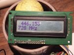
; ghzfm.000 Added multiply by 64
; Rendered offsets ineffective
; changed display format to
; xxxx.xxxxxx MHz
; Gate time now 1.000 Second
;
;
;
;*******************************************************************
;o-----o-----o-----o-----o-----o-----o-----o-----o-----o-----o-----o
;*******************************************************************
;
; Some frequently used code fragments
; Use macros to make mistreaks consistently.
;
;-------------------------------------------------------------------
; Select Register Bank 0
bank0 macro
errorlevel +302 ; Re-enable bank warning
bcf STATUS,RP0 ; Select Bank 0
endm
;-------------------------------------------------------------------
; Select Register Bank 1
bank1 macro
bsf STATUS,RP0 ; Select Bank 1
errorlevel -302 ; disable warning
endm
;-------------------------------------------------------------------
; Copy a 32 bit thing from one place to another
copy macro from,to
movf from+0,W
movwf to+0
movf from+1,W
movwf to+1
movf from+2,W
movwf to+2
movf from+3,W
movwf to+3
endm
;*******************************************************************
;
; CPU configuration
;
#ifdef F84
MESSG "Processor = 16F84"
#define RAMStart 0x0C ; by VK3BHR
processor 16f84
include <p16f84.inc>
__config _HS_OSC & _PWRTE_ON & _WDT_OFF
#endif
#ifdef F628
MESSG "Processor = 16F628"
#define RAMStart 0x20
processor 16f628
include <p16f628.inc>
__config _HS_OSC & _PWRTE_ON & _WDT_OFF & _CP_OFF & _BODEN_ON & _LVP_OFF
#endif
;*******************************************************************
;
; I/O configuration
;
#define S_out PORTA,0x00 ; 9600 baud serial out
#define PUFF PORTA,0x00 ; Testing counter out
;#define FIXIT PORTA,0x01 ; 1 = "good display"
; 0 = do CRLF at "chr 8"
#define PSC PORTA,0x01 ; 1 = multiply by 64
#define ENA PORTA,0x02 ; Display "E"
#define RS PORTA,0x03 ; Display "RS"
#define CLAMP PORTA,0x04 ; Pull-down the timer input
#define Store PORTB,0x04 ; Pin 10, 0 = Measure BFO
#define Add_LO PORTB,0x05 ; Pin 11, 0 = RF := LO + IF
; 1 = RF := | LO + (-IF) |
#define BFO_Lo PORTB,0x06 ; Pin 12, 0 = BFO on lower freq.
#define BFO_Hi PORTB,0x07 ; Pin 13, 0 = BFO on higher freq.
#define Prg_FLG FLAGS,0x05
#define AMflag FLAGS,0x03 ; 0 = Don't print USB/LSB suffix
#define beq bz ; Motorola syntax branches
#define BEQ bz
#define BNE bnz
#define bne bnz
#define BCC bnc
#define bcc bnc
#define BCS bc
#define bcs bc
#define BRA goto
#define bra goto
;*******************************************************************
;
; file register declarations: uses only registers in bank0
; bank 0 file registers begin at 0x20 in the 16F628
;
;*******************************************************************
cblock RAMStart
dbg0:4 ; Debugging stuff
dbg1:4
dbg2:4
dbg3:4
dbg4:4
dbg5:4
bcd:5 ; BCD, MSD first
SBflag ; 0 = Lower BFO frequency
; 1 = Higher
COUNT ; Bin to BCD convert (bit count)
cnt ; (BCD BYTES)
CHR
TEMP ; DATS/Putchr temporary
pmsg_t ; Used by PMSG
FLAGS
S_Wtemp ; "debug" Variables
S_count
D_Wtemp
D_Stemp
D_FSR
D_hex
endc
#ifdef F84
Part2 equ D_hex+1 ; Just tack on end
#endif
#ifdef F628
Part2 equ 0x70 ; $70-7F Visible from all banks
#endif
cblock Part2
COUNT1 ; Used by delay routines
COUNT2 ; Timing (100ms)
COUNT3 ; Timing (100ms)
COUNT4 ; Timing (400ms)
AccA:4 ; Binary, MSByte first
AccB:4 ; Intermediate frequency
Hold:4 ; Used in "cal" mode
endc
;**********************************************************
;
; Begin Executable Stuff(tm)
;
org 0
GO clrwdt ; 0 << Reset
clrf INTCON ; 1 No interrupts
#ifdef F628
movlw 0x07 ; 2 Comparator off
movwf CMCON ; 3
#endif
goto START ; 4 << Interrupt.
;**********************************************************
;
; Part of string printer
;
pmsub movwf PCL ; Goto W
nop ; Just in case
pm_end return
;**********************************************************
;
; Text Strings (stored in RETLWs)
;
mhz dt " MHz",0
Spaces dt " ",0
USB dt "U",0
LSB dt "L",0
Prog dt "P",0
Cal dt "C",0
#ifdef Two_Line
adv3 dt "1234567890ABCDEF",0
endif
;**********************************************************
;
; Main Program
;
START call InitIO ; INITIALISE PORTS
CLRF PORTA
CLRF PORTB
bsf S_out ; Serial output to idle
CALL LCDINIT ; INITIALIZE LCD MODULE
; MOVLW adv1 ; Sign on
; call pmsg
; btfss FIXIT ; Test input 1 = just return
; CALL LINE2 ; 0 = fix bad display
; movlw adv2
; call pmsg
; CALL MS512 ; Delay for about 1 sec.
; CALL MS512 ; 0.512 sec x 2
CALL CLEAR
;**********************************************************
;
; Check if in "Calibrate" mode
;
btfsc Store ; If grounded initially
goto newbit ; then were in "cal"
MOVLW 0xfa ; Set initial counter
MOVWF Hold+0 ; value
MOVLW 0xff ;
MOVWF Hold+1 ; for a 4 MHZ XTAL
MOVLW 0x5f
MOVWF Hold+2
MOVLW 0x00 ; Unused
MOVWF Hold+3
GetCal call Measure
call Display
movlw Cal ; Say "we're calibrating"
call pmsg
CALL HOME
;
; Adjust Cal value
;
cal_dn btfsc BFO_Lo
goto cal_up
incf Hold+2,f ; Add 1
bne inc_xit
incf Hold+1,f
bne inc_xit
incf Hold+0,f
inc_xit goto StorCal
cal_up btfsc BFO_Hi
goto StorCal
;
; Hold := Hold + (1-) ; Subtract 1
;
Hadd_2 movlw 0xff ; Process LS byte
addwf Hold+2,F
bcc Hadd_1 ; If no carry,do next
incf Hold+1,f ; Else roll over higher
bne Hadd_1 ; bytes as appropriate
incf Hold+0,f ; may roll over MSByte
Hadd_1 movlw 0xff ; Process next byte
addwf Hold+1,F
bcc Hadd_0 ; If no carry,do next
incf Hold+0,f ; may roll over MSByte
Hadd_0 movlw 0xff ; Process next byte
addwf Hold+0,F
;
; Time to save "Cal" value?
;
StorCal btfss Store ; Ready to store it?
goto GetCal
call MS512 ; Delay 0.5 sec
btfss Store ; De-bounce
goto GetCal
copy Hold,AccB ; Write EEPROM from AccB
movlw 0x10 ; EEADR of Cal value
call EE_WR
;**********************************************************
;
; Begin a new measurement cycle
;
newbit movlw 0x10 ; EEADR of Cal value
call EE_RD ; in AccB
copy AccB,Hold ; Get timing "constant"
call HOME ; Display ready
clrf SBflag ; 0 = Lower BFO frequency
; 1 = Higher
bcf AMflag ; 0 = No USB/LSB suffix
bcf Prg_FLG
btfsc Store ; Doing "BFO STORE"?
goto GetOffs
call MS512 ; Delay 0.5 sec
btfsc Store ; De-bounce
goto GetOffs
GetIf call Measure ; Get freq in AccA:4
copy AccA,AccB ; For EEPROM Writing
call Display ; Display freq in AccA
movlw Prog ; Say "we're programming"
call pmsg
CALL HOME
btfss Store ; Ready to store it?
goto GetIf
call MS512 ; Delay 0.5 sec
btfss Store ; De-bounce
goto GetIf
bsf Prg_FLG ; Flag "to be stored"
GetOffs btfss BFO_Hi ; Which Offset??
goto Get2 ; Point @ EEPROM
btfss BFO_Lo ; 4 bytes each
goto Ch2 ; BFO low link only
goto Ch3 ; No links
Get2 btfss BFO_Lo
goto Ch0 ; Both links
goto Ch1 ; BFO high link only
Ch0 movlw 0x00 ; Offset channel 0 (both links fitted)
goto EndOff
Ch1 bsf AMflag ; We're gunna print
comf SBflag,f ; that BFO is on higher frequency
movlw 0x04 ; Offset channel 1 (BFO_Hi link fitted)
goto EndOff
Ch2 bsf AMflag ; We're gunna print
; that BFO is on lower frequency
movlw 0x08 ; Offset channel 2 (BFO_Lo link fitted)
goto EndOff
Ch3 movlw 0x0C ; Offset channel 3 (no links fitted)
; goto EndOff
EndOff btfsc Prg_FLG ; Storing Offset?
goto Do_St ; If not, then
call EE_RD ; must be reading.
goto Do_Meas
Do_St call EE_WR
;
; Now have IF in AccB
;
Do_Meas call Measure ; Measure Local Osc Freq.
;
; Now have LO in "AccA"
; and IF in "AccB"
;
Add_Sub btfss Add_LO ; Add or Sub LO freq?
goto AddLSB ; Clear = just add
call MinusA ; RF := |IF - LO|
; SBflag is OK
AddLSB call AplusB
;
; Fix overflow. If negative then make positive
;
btfss AccA+0,7 ; Set? (=Overflow)
goto OK2go ; Clear = OK 2 print
call MinusA ; Make positive and
comf SBflag,f ; Swap USB/LSB
;
; Display resulting number in AccA
;
OK2go call Display ; display result at last
;
; Print suffix - USB, LSB or nuffin
; Now disabled
btfsc AMflag ; Do we print at all?
goto trySBf
movlw Spaces ; nuffin = spaces
goto EndMsg
trySBf btfsc SBflag,0 ; Which sideband?
goto pLSB
movlw USB ; USB obviously
goto EndMsg
pLSB movlw LSB ; LSB
; goto EndMsg
EndMsg call pmsg ; Print selected trailer
#ifdef Two_Line
CALL LINE2 ; WRITE second LINE
movlw adv3
call pmsg
endif
goto newbit ; Start next measurement
;**********************************************************
;
; AccA := AccA + AccB
;
AplusB movf AccB+3,W ; Process LSB
addwf AccA+3,F
bcc Add_2 ; If no carry,do next
incf AccA+2,f ; Else roll over higher
bne Add_2 ; bytes as appropriate
incf AccA+1,f
bne Add_2
incf AccA+0,f ; may roll over MSByte
Add_2 movf AccB+2,W ; Process next byte
addwf AccA+2,F
bcc Add_1 ; If no carry,do next
incf AccA+1,f ; Else roll over higher
bne Add_1 ; bytes as appropriate
incf AccA+0,f ; may roll over MSByte
Add_1 movf AccB+1,W ; Process next byte
addwf AccA+1,F
bcc Add_0 ; If no carry,do next
incf AccA+0,f ; may roll over MSByte
Add_0 movf AccB+0,W ; Process next byte
addwf AccA+0,F
return
;**********************************************************
;
; Negate number in AccA (2's complement form)
;
MinusA comf AccA+0,f ; Complement all bits
comf AccA+1,f ; of number
comf AccA+2,f
comf AccA+3,f
incf AccA+3,f ; Add 1
bne N_xit
incf AccA+2,f
bne N_xit
incf AccA+1,f
bne N_xit
incf AccA+0,f
N_xit return
;**********************************************************
;
; Divide AccA:4 by 4
;
;**********************************************************
Div4 call Div2 ; Divide AccA:4 by 4
;**********************************************************
;
; Divide AccA:4 by 2
;
;**********************************************************
Div2 rrf AccA+0,f
rrf AccA+1,f
rrf AccA+2,f
rrf AccA+3,f
bcf AccA+0,7 ; Possible bad carry in.
return
;**********************************************************
;
; Multiply AccA:4 by 64
;
;**********************************************************
Mul64 call Mul2
call Mul2
call Mul2
call Mul2
call Mul2 ; then fall through
call Mul2
call Mul2
;**********************************************************
;
; Multiply AccA:4 by 2
;
;**********************************************************
Mul2 rlf AccA+3,f
rlf AccA+2,f
rlf AccA+1,f
rlf AccA+0,f
bcf AccA+3,0 ; Possible bad carry in.
return
;**********************************************************
;
; Print String addressed by W
; Note: Strings are in program space
;
pmsg movwf pmsg_t ; Temp for pointer
pm1 movf pmsg_t,W ; Get current pointer
call pmsub
andlw 0xff ; Test returned value
beq pm_end ; NULL = All done
call DATS
incf pmsg_t,F
goto pm1
;**********************************************************
;
; Delay for 1000ms (trimmed for actual clock freq)
; Check for Timer register roll over and count 'em
;
; Uses: W, COUUNT1, COUNT2, COUNT3 & others
;
;**********************************************************
MS1000 MOVF Hold+0,w ; 100 MS DELAY LOOP
MOVWF COUNT1 ; 4 MHZ XTAL
MOVF Hold+1,w ; Count up
MOVWF COUNT2 ; to 24 bit overflow
MOVF Hold+2,w
MOVWF COUNT3
L3 INCFSZ COUNT3,F
GOTO L3
call RollOver ; Check for Timer0 RollOver
INCFSZ COUNT2,F
GOTO L3
INCFSZ COUNT1,F
GOTO L3
RETLW 0
;**********************************************************
;
; SEND A COMMAND BYTE TO LCD DISPLAY MODULE
;
STROBE BCF RS ; SELECT COMMAND REGISTER
GOTO CM
;**********************************************************
;
; Put a BCD nybble to display
;
PutNyb ANDLW 0x0F ; MASK OFF OTHER PACKED BCD DIGIT
ADDLW 0x30 ; Convert BIN to ASCII
;**********************************************************
;
; Put a data byte to display
;
DATS movwf TEMP ; Save character for LCD
call putchr
movf TEMP,w
BSF RS ; SELECT DATA REGISTER
CM MOVWF CHR ; STORE CHAR TO DISPLAY
SWAPF CHR,W ; SWAP UPPER AND LOWER NIBBLES (4 BIT MODE)
call PB_dly
MOVF CHR,W ; GET CHAR AGAIN
;**********************************************************
;
; Put 4 bits to LCD & wait (untrimmed)
;
PB_dly ANDLW 0x0F ; MASK OFF UPPER 4 BITS
MOVWF PORTB ; SEND DATA TO DISPLAY
BSF ENA ; ENA HIGH
NOP
BCF ENA ; ENA LOW
; Fall into 200us DELAY subroutine
;**********************************************************
;
; Delay for 200us (untrimmed)
;
; Uses: W, COUNT1
;
;**********************************************************
D200us
DELAY MOVLW 0x42 ; DELAY 200us
MOVWF COUNT1
NXT5 DECFSZ COUNT1,F
GOTO NXT5
RETLW 0
;**********************************************************
;
; Delay for 2ms (untrimmed)
;
; Uses: W, COUNT2, COUNT1
;
;**********************************************************
MS2 MOVLW 0x0A ; DELAY 2ms
MOVWF COUNT2
LP15 call D200us
DECFSZ COUNT2,F
GOTO LP15
RETLW 0
;**********************************************************
;
; Delay for 512ms (untrimmed)
;
; Uses: W, COUNT3, COUNT2, COUNT1
;
;**********************************************************
MS512 clrw ; 0 -> 256 loops
;**********************************************************
;
; Delay for multiples of 2ms (untrimmed)
;
; Uses: W, COUNT3, COUNT2, COUNT1
;
;**********************************************************
MS2xW MOVWF COUNT3
LPx15 call MS2
DECFSZ COUNT3,F
GOTO LPx15
RETLW 0
;******************************************************************
;
; Convert 32-bit binary number at <AccA:4> into a bcd number
; at <bcd:5>. Uses Mike Keitz's procedure for handling bcd
; adjust. Microchip AN526
;
B2_BCD
b2bcd movlw .32 ; 32-bits
movwf COUNT ; make cycle counter
clrf bcd+0 ; clear result area
clrf bcd+1
clrf bcd+2
clrf bcd+3
clrf bcd+4
b2bcd2 movlw bcd ; make pointer
movwf FSR
movlw .5 ; Number of BCD bytes?
movwf cnt ; 2 BCD digits per byte
; Mike's routine:
b2bcd3 movlw 0x33
addwf INDF,f ; add to both nybbles
btfsc INDF,3 ; test if low result > 7
andlw 0xf0 ; low result >7 so take the 3 out
btfsc INDF,7 ; test if high result > 7
andlw 0x0f ; high result > 7 so ok
subwf INDF,f ; any results <= 7, subtract back
incf FSR,f ; point to next
decfsz cnt,f
goto b2bcd3
rlf AccA+3,f ; get another bit
rlf AccA+2,f
rlf AccA+1,f
rlf AccA+0,f
rlf bcd+4,f ; put it into bcd
rlf bcd+3,f
rlf bcd+2,f
rlf bcd+1,f
rlf bcd+0,f
decfsz COUNT,f ; all done?
goto b2bcd2 ; no, loop
return ; yes
;*********** INITIALISE LCD MODULE 4 BIT MODE ***********************
LCDINIT CALL MS512 ; Wait 0.512 sec for LCD RESET
BCF RS ; REGISTER SELECT LOW
BCF ENA ; ENABLE LINE LOW
MOVLW 0x03 ; 1
call PB_dly
CALL MS512 ; WAIT FOR DISPLAY TO CATCH UP
MOVLW 0x03 ; 2
call PB_dly
MOVLW 0x03 ; 3
call PB_dly
MOVLW 0x02 ; Fn set 4 bits
call PB_dly
MOVLW 0x28 ; DISPLAY 2 Line , 5x7 Dot's
CALL STROBE ; Suggested by PA0EJH
CALL DELAY
MOVLW 0x0C ; 0x0C DISPLAY ON
CALL STROBE
CALL DELAY
MOVLW 0x06 ; 0x06 ENTRY MODE SET
CALL STROBE
CALL DELAY
MOVLW 0x01 ; 0x01 CLEAR DISPLAY
CALL STROBE
CALL MS2
RETLW 0
;************ MOVE TO START OF LINE 2 *****************
LINE2 MOVLW 0xC0 ; ADDRESS FOR SECOND LINE OF DISPLAY
CALL STROBE
goto DELAY
;************ CLEAR DISPLAY ***************************
CLEAR MOVLW 0x01 ; COMMAND TO CLEAR DISPLAY
CALL STROBE
goto MS2 ; LONGER DELAY NEEDED WHEN CLEARING DISPLAY
;*********** MOVE TO HOME *****************************
HOME call crlf ; Serial
MOVLW 0x02 ; COMMAND TO HOME LCD DISPLAY
CALL STROBE
goto MS2
;********************************************************************
; Initialise Input & Output devices
;********************************************************************
InitIO bank1
movlw 0x37 ; Option register
movwf OPTION_REG ; Port B weak pull-up enabled
; INTDEG Don't care
; Count RA4/T0CKI
; Count on falling edge
; Prescale Timer/counter
; divide Timer/counter by 256
; PORTA:-
movlw 0x02 ; initialise data direction
; 1 = input, 0 = output
;
; PORTA has 5 pins 4 3 2 1 0
; 0x02 = 0 0 0 0 0 0 1 0
;
movwf TRISA ; PORTA<0> = Serial + Debugging Out
; PORTA<1> = FIXIT (input)
; PORTA<2> = LCD "E" Out
; PORTA<3> = LCD "RS" Out
; PORTA<4> = "Input" with pull-down
; Actually an output.
; PORTA<5:7> = not implemented in 16F84
;
; PORTB:-
movlw 0xf0 ; initialise data direction
; PORTB has 8 pins
; port pin 7 6 5 4 3 2 1 0
; 0xf0 = 1 1 1 1 0 0 0 0
;
movwf TRISB ; PORTB<0> = LCD "DB4"
; PORTB<1> = "DB5"
; PORTB<2> = "DB6"
; PORTB<3> = "DB7"
; PORTB<4> = Input
; PORTB<5> = Input
; PORTB<6> = Input
; PORTB<7> = Input
bank0
return
;**********************************************************
;
; Measure Frequency. Stash in "AccA:4"
;
Measure bcf CLAMP ; CLOSE GATE for safety
bsf PORTB,2 ; For compatibility with
bsf PORTB,3 ; Version 1 hardware
bcf INTCON,T0IF ; Clear any previous overflow
CLRF TMR0 ; RESET INTERNAL COUNT (INCLUDING PRESCALER)
; See page 27 Section 6.0
CLRF AccA+0 ; Ready to receive 32 bit number
CLRF AccA+1
CLRF AccA+2
CLRF AccA+3
bsf CLAMP ; OPEN GATE
CALL MS1000 ; 1.0 sec DELAY
bcf CLAMP ; CLOSE GATE (COUNT COMPLETE)
nop ; and allow time for
nop ; the registers to catch up
nop
nop
nop
call RollOver ; Final check, just in case
MOVF TMR0,W
MOVWF AccA+2
; Now empty the prescaler
PSC1 bank1
bcf OPTION_REG,T0SE ; Clock the prescaler
nop
bsf OPTION_REG,T0SE
bank0
DECF AccA+3,F ; Decrement the counter
movf TMR0,W ; Has TMR0 changed?
xorwf AccA+2,W ; if unchanged, XOR -> 0
beq PSC1
; AccA : AccA+1 : AccA+2 : AccA+3 now holds 32 bit result
; Rollover subroutine has set AccA+0 and AccA+1 suitably.
return
;**********************************************************
;
; Account for TMR0 overflows when counting
; Check at regular intervals and handle as
; necessary.
;
; Needs to be done at less than 936us (@ 70MHz in)
; intervals, or else it can lose counts.
;
RollOver
btfss INTCON,T0IF ; Rolled over?
goto RO3 ; No
RO1 bcf INTCON,T0IF ; Yes. ACK!
INCF AccA+1,f ; Count it
bne RO2 ; Overflowed?
incf AccA+0,f ; No need to check
RO2 return
; Balance path lengths
RO3 nop
nop
goto RO2
;**********************************************************
;
; Display frequency
;
; Display contents of AccA+0...AccA+3 on LCD
; First convert to BCD, Then ASCII (nybble at a time)
;
; In this version, multiply ACCA:4 by 64 since gate
; time = 1.0 second and ext prescale=64
;
Display btfsc PSC ; 1 = prescaler active = *64
call Mul64 ; Account for prescaler
CALL B2_BCD ; CONVERT all AccA TO BCD
; Perform Leading Zero Blanking on first 3 digits
swapf bcd+0,W ; 1000's of MHz
andlw 0x0F ; MASK OFF OTHER PACKED BCD DIGIT
bne NoB1K
MOVLW 0x20 ; YES PRINT A BLANK SPACE
CALL DATS
movf bcd+0,W ; 100's of MHz
andlw 0x0F ; MASK OFF OTHER PACKED BCD DIGIT
bne NoB100
MOVLW 0x20 ; YES PRINT A BLANK SPACE
CALL DATS
swapf bcd+1,W ; 10's of MHz
andlw 0x0F ; MASK OFF OTHER PACKED BCD DIGIT
bne NoB10
MOVLW 0x20 ; YES PRINT A BLANK SPACE
CALL DATS
goto NoB1
; Handle rest of number non blanked
NoB1K SWAPF bcd+0,W ; 1000's of MHz
CALL PutNyb
NoB100 MOVF bcd+0,W ; 100's of MHz
CALL PutNyb
NoB10 SWAPF bcd+1,W ; 10's of MHz
CALL PutNyb
NoB1 MOVF bcd+1,W ; 1's of MHz
CALL PutNyb
MOVLW '.' ; Decimal Point
CALL DATS
SWAPF bcd+2,W ; 100's of KHz
CALL PutNyb
MOVF bcd+2,W ; 10's of KHz
CALL PutNyb
SWAPF bcd+3,W ; 1's of KHz
CALL PutNyb
; CALL LINE2
MOVLW ',' ; Decimal Coma
CALL DATS
MOVF bcd+3,W ; 100's of Hz
CALL PutNyb
SWAPF bcd+4,W ; 10's of Hz
CALL PutNyb
MOVF bcd+4,W ; 1's of Hz
CALL PutNyb
movlw mhz ; WRITE " Mhz" AT end OF LINE
goto pmsg ; includes RETURN
;********************************************************************
; Read EEPROM into "AccB" (AccB must be visible in both
; W -> memory to read memory banks 0 & 1)
;********************************************************************
EE_RD
#ifdef F628
bank1
#endif
MOVWF EEADR ; Address to read
#ifdef F628
bank0
#endif
XORLW 0x0C ; Special case (no links)
BEQ AVERAGE
CALL EE_R
MOVWF AccB+0
CALL EE_Rinc
MOVWF AccB+1
CALL EE_Rinc
MOVWF AccB+2
CALL EE_Rinc
MOVWF AccB+3
RETURN
;--------------------------------------------------------------------
#ifdef F84
EE_Rinc INCF EEADR,F ; bump address
EE_R bank1
BSF EECON1,RD ; EE Read
bank0
MOVF EEDATA,W ; W = EEDATA
RETURN
#endif
;--------------------------------------------------------------------
#ifdef F628
EE_Rinc bank1
INCF EEADR,F ; bump address
EE_R bank1
BSF EECON1,RD ; EE Read
MOVF EEDATA,W ; W = EEDATA
bank0
RETURN
#endif
;--------------------------------------------------------------------
AVERAGE movlw 0x04 ; AM - use avg BFO freq.
call EE_RD ; Read in one BFO freq
copy AccB,AccA ; Into AccA
movlw 0x08 ; Then second
call EE_RD ; into AccB
call AplusB ; Add 'em
call Div2 ; get average in AccA
copy AccA,AccB ; and in AccB
return
;********************************************************************
; Write EEPROM from "AccB" (AccB must be visible in both
; W -> memory to write memory banks 0 & 1)
;********************************************************************
#ifdef F84
EE_WR MOVWF EEADR ; Address to write
MOVF AccB+0,W ; Data byte #0
CALL EE_W
MOVF AccB+1,W ; Data byte #1
CALL EE_Winc
MOVF AccB+2,W ; Data byte #2
CALL EE_Winc
MOVF AccB+3,W ; Data byte #3
CALL EE_Winc
RETURN
EE_Winc INCF EEADR,F ; bump address
EE_W MOVWF EEDATA
bank1
BSF EECON1,WREN ; Enable Write
MOVLW 0x55 ;
MOVWF EECON2 ; Write 0x55
MOVLW 0xAA ;
MOVWF EECON2 ; Write 0xAA
BSF EECON1,WR ; Set WR bit (begin write)
EE_W2 BTFSC EECON1,WR ; Wait for write to finish
GOTO EE_W2
BCF EECON1,EEIF ; clear interrupts
bank0
RETURN
#endif
;--------------------------------------------------------------------
#ifdef F628
EE_WR bank1
MOVWF EEADR ; Address to write
MOVF AccB+0,W ; Data byte #0
CALL EE_W
MOVF AccB+1,W ; Data byte #1
CALL EE_Winc
MOVF AccB+2,W ; Data byte #2
CALL EE_Winc
MOVF AccB+3,W ; Data byte #3
CALL EE_Winc
bank0
RETURN
errorlevel -302 ; In Bank 2
EE_Winc INCF EEADR,F ; bump address
EE_W MOVWF EEDATA
BSF EECON1,WREN ; Enable Write
MOVLW 0x55 ;
MOVWF EECON2 ; Write 0x55
MOVLW 0xAA ;
MOVWF EECON2 ; Write 0xAA
BSF EECON1,WR ; Set WR bit (begin write)
EE_W2 BTFSC EECON1,WR ; Wait for write to finish
GOTO EE_W2
bank0
BCF PIR1,EEIF ; clear interrupts
bank1
RETURN
errorlevel +302
#endif
;********************************************************************
; Testing counter
;********************************************************************
ctest movlw 0xfe ; MS byte of loop count
movwf COUNT3 ; Counted upward till it overflows
movlw 0x1d
movwf COUNT2
movlw 0xc0
movwf COUNT1
cloop bcf PUFF ; Toggle counter input once
bsf PUFF
incfsz COUNT1,f
goto cloop
incfsz COUNT2,f
goto cloop
incfsz COUNT3,f
goto cloop
return
;***********************************************************************
;
; Debugging Memory & Register dump
;
debug
MOVWF D_Wtemp ; Copy W to temp register,
SWAPF STATUS,W ; Swap status to be saved into W
MOVWF D_Stemp ; Save status to D_Stemp register
movf FSR,W ; Save FSR
movwf D_FSR
movlw 0x57 ; W=
call putchr
movlw 0x3d
call putchr
movf D_Wtemp,w
call hex_2
movlw 0x20 ; 2 spaces, just to be neat
call putchr
movlw 0x20
call putchr
movlw 0x53 ; SR=
call putchr
movlw 0x52
call putchr
movlw 0x3d
call putchr
movf D_Stemp,w
call hex_2
call crlf ; Serial
clrf FSR ; Ready for memory dump
D_loop movf 0,W ; Read indirect
call hex_2
movlw 0x20
call putchr
incf FSR,f ; to next byte
movf FSR,w ; end of line?
andlw 0x0F
bne next_ln
call crlf
bra chk4end
next_ln andlw 0x03 ; Groups of 4
bne chk4end
movlw 0x20
call putchr
chk4end movf FSR,w ; All done?
xorlw 0x80
bne D_loop
call crlf
call crlf
movf D_FSR,W ; Restore FSR
movwf FSR
SWAPF D_Stemp,W ; Swap nibbles in D_Stemp register
; and place result into W
MOVWF STATUS ; Move W into STATUS register
; (sets bank to original state)
SWAPF D_Wtemp,F ; Swap nibbles in D_Wtemp and place result in D_Wtemp
SWAPF D_Wtemp,W ; Swap nibbles in D_Wtemp and place result into W
return
;***********************************************************************
;
; Print CRLF to serial
;
crlf movlw 0x0d ; CRLF
call putchr
movlw 0x0a
goto putchr
;***********************************************************************
;
; Print W as 2 Hex digits
;
hex_2 movwf D_hex
swapf D_hex,w ; Get big bit
call hex_3
movf D_hex,w ; Get little bit
hex_3 andlw 0x0f ; keep bottom 4 bits
addlw 0xF6
bcc hex_4
addlw 0x07 ; binary A -> ASCII A
hex_4 addlw 0x3A ; binary 0 -> ASCII 0
; goto putchr
;********************************************************
;
; Output Routines for PIC16F84
;
; Clock is 4.0 MHz.
; ie. 1.0 us per cycle = 4/Fosc.
;
; 9600 Baud = 104.17 us
; = 104.17 CPU cycles
;
;********************************************************
;
; Output the character in W. Assumes Mac is ready.
;
; Uses W
;
putchr movwf S_Wtemp ; Character being output
movlw 0x08 ; Bit count
movwf S_count
bcf S_out ; Send a 0 - Start bit
put_clp movlw 0xE7 ; Delay "104" cycles
txd_0 addlw 0x01
bne txd_0
rrf S_Wtemp,f ; Transmit a bit
bcs t_0
bcf S_out ; Send a 0
bra tx_1
t_0 bsf S_out ; Send a 1
tx_1 decfsz S_count,f ; Done all bits?
goto put_clp
movlw 0xE7 ; Delay for last data
txd_1 addlw 0x01
bne txd_1
bsf S_out ; Transmit two stop bit
movlw 0xCD
txd_9 addlw 0x01
bne txd_9
return
;********************************************************************
; Tail End Charlie
;********************************************************************
; initialize eeprom locations
ORG 0x2100
DE 0x00, 0x00, 0x00, 0x00 ; Unused (reserved for later)
DE 0x00, 0x00, 0x00, 0x00 ; IF Offset 1 Low BFO ????
DE 0x00, 0x00, 0x00, 0x00 ; IF Offset 2 High BFO ????
DE 0x00, 0x00, 0x00, 0x00 ; IF Offset 3 No BFO -AM-
DE 0xfa, 0xff, 0x5f, 0x00 ; 4.000 MHz initial calibration
END


")