Amigos tengo un problema y necesito solucionarlo lo mas pronto posible con la ayuda de ustedes, ya que es un proyectico de la u.
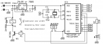
Estoy realizando un proyecto sencillo de una cerradura electroinica que consulte en esta pagina http://jap.hu/electronic/combination_lock.html me iagino que alguno de ustedes ya la conoce. este es el esquema.
Ya lo he montado, el problema surge con el pìc, grabo el .hex con el winpic y todo ok. pero cuando lo manto en el circuito no hace absolutamente nada, nisiquiera pita, me parece super raro, probe con otro quemador de pics y igual, todo ok pero el el montaje nada de nada, este es el codigo fuente,
;**********************************************************************
; *
; Filename: cl2.asm *
; Date: *
; File Version: Combination lock rewritten *
; *
; Author: el@jap.hu *
; http://jap.hu/electronic/ *
;**********************************************************************
;NOTES
;
; the rewritten combination lock has the following changes:
;
; - no multiplexer is needed (the old version used a generic devboard)
; - no row diodes needed (rows are never driven HIGH)
; - low power consumption due to keyboard wake-up
; - stores the code in the internal EEPROM
; - user defined codelength and pulse output
; - user adjustable running frequency
; - improved code changing function with a "change" indicator LED
;
; PIC ports used:
;
; PA0-3 outputs: row select pulldown outputs (tristate or driven LOW)
; PB1 output: code change indicator LED
; PB2 output: output pulse to control a relay
; PB3 output: piezo beeper output
; PB4-PB7 inputs: column inputs with internal pullup
;
;**********************************************************************
;HISTORY
;
; 020-20010929 rewrite started
; 021-20011022 udelay calibrated to 100 usec (4, 10 MHz)
; 022-20011022 scan, input and compare functions work
; 023-20011022 code change function works
;
;**********************************************************************
list p=16f84a
__CONFIG _CP_OFF & _WDT_OFF & _PWRTE_ON & _HS_OSC
#include <p16F84a.inc>
mhz EQU D'10' ; processor frequency in MHz
pulsewidth EQU D'150'; delay in 20ms steps (150=3 sec)
clen EQU 4 ; length of code
; EEPROM contents
ORG 0x2100
de "123456" ; default code (clen chars are used)
; which is stored in EEPROM
; RAM registers
ram_start EQU 0x0c
dcnt0 EQU ram_start+1 ; delay counter 0
dcnt1 EQU ram_start+2 ; delay counter 1
dcnt2 EQU ram_start+3 ; delay counter 2
beepcnt EQU ram_start+4 ; beep cycle counter
keycode EQU ram_start+5
rowcnt EQU ram_start+6
colcnt EQU ram_start+7
colstatus EQU ram_start+8
cod EQU ram_start+9 ; actual code
cod_end EQU cod+clen
readlen EQU cod_end
readbuf EQU cod_end+1
readbuf_end EQU readbuf+clen
tmptr EQU readbuf_end ; pointer for comparing and copying readbuf
tmbyte EQU readbuf_end+1; temp storage for comparing and copying
vectors ORG 0
goto main
nop
nop
nop
retfie
keytable ;determine pressed key's real code from scancode
movf keycode, W
addwf PCL, F
dt 0x60
dt "123a"
dt "456b"
dt "789c"
dt "*0#d"
eep_read ; read EEPROM contents to RAM from cod to cod_end-1
movlw cod
movwf FSR
clrf EEADR
eep_0 ;bcf INTCON, GIE
bsf STATUS, RP0
bsf EECON1, RD
bcf STATUS, RP0
;bsf INTCON, GIE
movf EEDATA, W
movwf INDF
incf FSR, F
incf EEADR, F
movlw cod_end
subwf FSR, W
bnz eep_0
return
eep_write ; save RAM contents to EEPROM from cod to cod_end-1
movlw cod
movwf FSR
clrf EEADR
eep_1 movf INDF, W
movwf EEDATA
;bcf INTCON, GIE
bsf STATUS, RP0
bcf EECON1, EEIF
bsf EECON1, WREN
movlw 0x55
movwf EECON2
movlw 0xaa
movwf EECON2
bsf EECON1, WR
; wait for write completition
eep_2 bcf STATUS, RP0
;bsf INTCON, GIE
nop
nop
;bcf INTCON, GIE
bsf STATUS, RP0
btfss EECON1, EEIF
goto eep_2
bcf STATUS, RP0
;bsf INTCON, GIE
incf FSR, F
incf EEADR, F
movlw cod_end
subwf FSR, W
bnz eep_1
return
udelay ; delay W * 100 usec
movwf dcnt0
udelay0 movlw 8 * mhz
movwf dcnt1
udelay1 decfsz dcnt1, F
goto udelay1
decfsz dcnt0, F
goto udelay0
return
beep movwf beepcnt
beep0 bsf PORTB, 3 ; beepctl bit
movlw 3
call udelay
bcf PORTB, 3 ; beepctl bit
movlw 3
call udelay
decfsz beepcnt, F
goto beep0
return
keyscan ; scan the keyboard
clrf keycode
movlw 4
movwf rowcnt
movlw 0xfe
tris PORTA ; select row 0
rowscan movlw 0xa0
call udelay
swapf PORTB, W
movwf colstatus
movlw 4
movwf colcnt
colscan incf keycode, F
rrf colstatus, F
btfss STATUS, C
goto keytable ; a key was found
decfsz colcnt, F
goto colscan
bsf STATUS, C
bsf STATUS, RP0
rlf TRISA, F ; select next row
bcf STATUS, RP0
decfsz rowcnt, F
goto rowscan
retlw 0 ; no key was found
main ; program starts here
clrf PORTA
clrw
tris PORTA ; porta all output
clrf PORTB
movlw 0xf0 ; pb4-7 inputs
tris PORTB
bsf STATUS, RP0 ; bank 1
bcf OPTION_REG, NOT_RBPU ;internal pullups on port B enabled
bcf STATUS, RP0 ;bank 0
warm movlw 0xf0
call beep
call eep_read ; read code from eeprom to ram at cod
loop clrf PORTB ; clear output
call read ; read code from keyboard into readbuf
movlw cod
call compbuf ; compare code in readbuf with code at cod
bnz loop ; the code is different
; the code matches, check which enter (#*) was pressed
movlw '*'
subwf keycode, W ; * changes code
bz codechange
pulseout ; # operates output
movlw 0x04 ; RB2 is output
movwf PORTB
movlw pulsewidth
movwf dcnt2
out0 movlw d'200'
call udelay
decfsz dcnt2, F
goto out0
goto loop
codechange movlw 2 ; * changes code
movwf PORTB ; indicate changing the code
call read ; read new code into readbuf
movlw cod
call copybuf ; copy new code into cod
call read ; read new code twice
movlw cod ; and check if the new code is confirmed
call compbuf ; wrong code entry, restart with the original code
bnz warm
; new code is comfirmed twice, store into eeprom
call eep_write
goto loop
read clrf readlen
readloop ; wait until no key is pressed
clrw
tris PORTA ; porta all LOW
movf PORTB, W
andlw 0xf0 ; keymask
xorlw 0xf0
btfss STATUS, Z
goto readloop
movlw 0xf0 ; wait 24 ms
call udelay ; (debounce)
; no key pressed, go to sleep
movf PORTB, W
movlw 1<<RBIE ; enable RB port change wake-up
movwf INTCON
sleep
key_pressed
call keyscan
andlw 0xff
movwf keycode
bz readloop
movlw 0xf0 ; wait 24 ms
call udelay ; (debounce)
; check if the buffer is full
movlw clen
subwf readlen, W
bnz read_notfull
; buffer is full, can return if an enter key (*#) is pressed
; check for ENTER
call read_chkenter
bnz read_notenter
; enter is pressed, return
movlw 0x40
call beep
movf keycode, W
return
read_notenter
; buffer is full, but more characters entered
; shift the buffer
movlw readbuf+1
movwf FSR
read_shift movf INDF, W
decf FSR, F
movwf INDF
incf FSR, F
incf FSR, F
movlw readbuf_end
subwf FSR, W
bnz read_shift
decf readlen, F
read_notfull call read_chkenter ; if the buffer is not full and an
bz read ; enter key (*#) is pressed, clear buffer
movlw 0x40
call beep
movlw readbuf
addwf readlen, W
movwf FSR
movf keycode, W
movwf INDF
incf readlen, F
goto readloop
read_chkenter ; check if a * or # is pressed which indicates
; the end of entry
movlw '#'
subwf keycode, W
btfsc STATUS, Z
return ; Z=1, enter
movlw '*'
subwf keycode, W
return
compbuf ; compare read buffer to a code in RAM at W
movwf tmptr ; compare pointer
clrf readlen ; compare index starts from 0
comp0 movlw readbuf
addwf readlen, W
movwf FSR
movf INDF, W
movwf tmbyte ; the read byte which is compared
movf tmptr, W
addwf readlen, W
movwf FSR
movf INDF, W ; the byte readbuf is compared to
subwf tmbyte, W
btfss STATUS, Z
return ; Z=0: the code is different
incf readlen, F
movlw clen
subwf readlen, W
bnz comp0 ; compare next character
; Z=1: the code is the same
return
copybuf ; copy readbuf to RAM at W
movwf tmptr ; copy pointer
clrf readlen ; copy index starts from 0
copy0 movlw readbuf
addwf readlen, W
movwf FSR
movf INDF, W
movwf tmbyte ; the read byte which is copied
movf tmptr, W
addwf readlen, W
movwf FSR
movf tmbyte, W ; the byte from readbuf
movwf INDF
incf readlen, F
movlw clen
subwf readlen, W
bnz copy0 ; copy next character
return
end
creo que el programa funciona bien ya que lo simule en proteus y trabaja de maravilla. no se si sera que el pic esta malo,pero entonces porque si graba y lo leo desde el winpic, lo verifico y todo ok, pero nada.
una duda el pin de MCLR puede ir directamente a VDD o seria mejor conectar una resistencia, y otra cosa en mi montaje puse un cristal de 4 Mhz pero el codigo dice que es para 10Mhz no se si sera ese el problema, conseguire uno de 10 haber que pasa, pero imagino que con 4 deberia al menos dar una señal de vida.
Espero me puedan ayudar es con el PIC16F84A