_____________________________________


The circuit diagram shows a single channel of my simple MOSFET power amplifier. For stereo applications two identical units would be required.
Although this amplifier was designed with simplicity and ease of construction as a primary goal, do not be mislead by its simplicity, it will compete with some of the best amplifiers around.
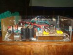
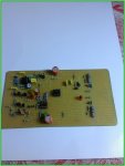
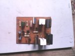
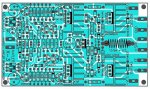
I have decided to make the board very compact and included the resevoir caps and rectifier bridge on board therefore only a power transformer is needed to make it work.
The output power is related to the power transformer rating that you choose to use. The table below shows approximate RMS power output for a particular transformer rating. The amplifier is stable with a supply voltage as low as +-12VDC, but this would be rather pointless as the power output will be only about 6 watts.
Transformer VAC VA Rating RMS Output
24 - 0 - 24 120 50 Watt 8 Ohms
30 - 0 - 30 180 75 Watt 8 Ohms
35 - 0 - 35 226 100 Watt 8 Ohms
If you are planning a stereo amplifier use two seperate power transformers, one for each channel as it does make for a far better sounding amplifier.
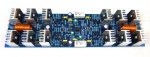
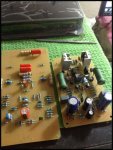
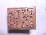
The circuit is very simple and uses two MPSA 56 (or BC 556C) as a differential input pair followed by BD 139-10 as differential VAS stage while a pair of BD 140-10 are used as a current mirror.
Interestingly, adding the current mirror made no difference to distortion, but reduced the DC offset to less than 20mV. The improvement was noteworthy.
The MOSFETS are Hitachi lateral devices, 2SK1058 (N-Channel) and 2SJ162 (P-Channel).
These are designed specifically for audio, and are far more linear than the more common switching devices that many MOSFET amps use.
Unfortunately, they are not cheap, but their performance in an audio circuit far exceeds vertical MOSFETS or HEXFETS.
Note that using HEXFETS or any other vertical MOSFET type is not an option. They will fail in this circuit!
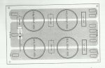
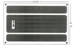
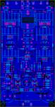
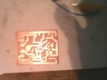
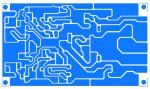
The most critical aspect of the design is the PCB layout, and it is very doubtful that if you make your own board, that you will get performance even approaching mine. Power output is essentially unchanged, but distortion and stability are achieved by a compact and carefully designed layout for the front end and driver circuits, which minimises any adverse PCB track coupling that causes much higher distortion levels, and may cause oscillation.
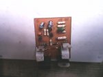
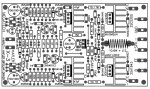
Please note: The output devices are mounted under the board facing up so that the whole board will be screwed down onto the heat sink. Remember to use silicon grease and mica whashers else you will be short circuiting the positive and negative power supplies.
Typical Amplifier Performance:
Maximum Output: • 100 watts RMS 8 Ohms, • 170 watts rms into 4 Ohms
Audio Frequency Linearity: • 20 Hz - 20 kHz (+0, -0.5 dB)
Closed Loop Gain: • 32 dB
Hum and Noise: • -92 dB (input short circuit)
Output Offset Voltage: • Less than 13 mV (input short circuit)
Phase Linearity: • Less than 13 0 (10 Hz - 20 kHz)
Harmonic Distortion: • Less than 0.008% at any power level
IM Distortion: • Less than .01% at maximum power


 Un-Sound.Com