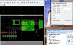
Bueno aqui les traigo unas cuantas practicas hechas con el compilador de microchip C18, Y sus respectivas simulaciones.
Algunas veces he notado que en las simulaciones no funciona correctamente, pero una veez armado fisicamente este funciona si ningun problema esto lo digo ya que simule un circuito que utilizaba una memoria eeprom 24c01B y en proteus no lo simulaba correctamente entonces me decidi armarlo y funciono perfectamente....Pero bueno empezare a poner mas programas cada vez que valla aprendiendo hacer mas interfaces tanto para i2c,spi,usart etc...ya que este compilador no ofrece tantas librerias, y uno tendra que hacerlas... pero es muy bueno ya que cuando te familiarisas seras un dotado en la programacion de microcontroladores...
Me cambie al C18 y ya que algunas cosas no entendia a cuanto a las librerias como GLCD, FAT16 etc del compilador CCS C.
Espero que sea de gran ayuda estos programas
Parpadeo de led...
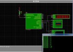
Configuracion del oscilador INterno y uso de la libreria USART
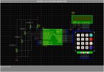
uso simple del xlcd
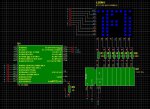
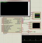
Otro uso del lcd con ADC
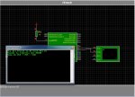
uso del usart con oscilador interno
otro uso del usart y pwm
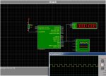
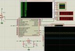
Otro uso del pwm,usart y adc
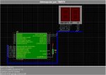
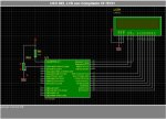
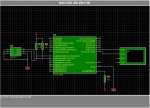
uso de memorias eeprom 24c01B
He invito a otras personas a colaborar en la programacion de este compilador tanto de uso de librerias hechas para este lenguaje ASCII, para que fuera una gran ayuda para llegar a programar correctamente estos pic18 y entender mas porque de las cosas....
Ya que tengo unas cuantas dudas en la programacion...como son
*Como importar librerias o hacer librerias para nuestros programas
*intruccion de lcd : putrsXLCD(const char*buffer), no funciona en proteus(no aparece nada escrito)
....
Algunas veces he notado que en las simulaciones no funciona correctamente, pero una veez armado fisicamente este funciona si ningun problema esto lo digo ya que simule un circuito que utilizaba una memoria eeprom 24c01B y en proteus no lo simulaba correctamente entonces me decidi armarlo y funciono perfectamente....Pero bueno empezare a poner mas programas cada vez que valla aprendiendo hacer mas interfaces tanto para i2c,spi,usart etc...ya que este compilador no ofrece tantas librerias, y uno tendra que hacerlas...
pero es muy bueno ya que cuando te familiarisas seras un dotado en la programacion de microcontroladores...Me cambie al C18 y ya que algunas cosas no entendia a cuanto a las librerias como GLCD, FAT16 etc del compilador CCS C.
Espero que sea de gran ayuda estos programas
Parpadeo de led...
Código:
#include<p18F2550.h>
#include <delays.h>

#pragma config FOSC = XT_XT,FCMEN = OFF,IESO = OFF, CPUDIV = OSC1_PLL2
#pragma config PWRT = ON,BOR = OFF,BORV = 0
#pragma config WDT = OFF,WDTPS = 32768
#pragma config MCLRE = ON,LPT1OSC = OFF,PBADEN = OFF,CCP2MX = OFF
#pragma config STVREN = OFF,LVP = OFF,XINST = OFF,DEBUG = OFF
#pragma config CP0 = ON,CP1 = ON,CP2 = ON
#pragma config CPB = ON,CPD = ON
#pragma config WRT0 = ON,WRT1 = ON,WRT2 = ON
#pragma config WRTB = ON,WRTC = ON,WRTD = ON
#pragma config EBTR0 = ON,EBTR1 = ON,EBTR2 = ON
#pragma config EBTRB = ON


void main (void)
{
    TRISB=0x00;
    while (1){
        PORTB=0x00;
        Delay10KTCYx(30);//Demora 300ms
        PORTB=0x01;
        Delay10KTCYx(30);//Demora 300ms
    }
}
Configuracion del oscilador INterno y uso de la libreria USART
Código:
#include<p18F2550.h>
#include<timers.h>


//Fuses para trabajar con 48Mhz/////////
#pragma config FOSC   = INTOSCIO_EC        //usamos 8Mhz internos
#pragma config PLLDIV = 5                //PLL DIV 20Mhz/5=4Mhz
#pragma config CPUDIV = OSC1_PLL2         //CPUDIV1 96Mhz/2=48Mhz
#pragma config USBDIV = 1                //tRABAJAMOS CON USB CLOCK divido en 1
#pragma config VREGEN = OFF                //Trabajamos sin regulador interno 3.3v para usb
//-----------------------------------------------------------------
#pragma config FCMEN  = OFF, IESO    = OFF
#pragma config PWRT   = ON, BOR     = OFF,BORV   = 0
#pragma config WDT    = OFF,WDTPS   = 32768
#pragma config MCLRE  = ON, LPT1OSC = OFF,PBADEN = OFF,CCP2MX = OFF
#pragma config STVREN = OFF,LVP     = OFF,XINST  = OFF,DEBUG  = OFF
#pragma config CP0    = OFF,CP1     = OFF,CP2    = OFF
#pragma config CPB    = ON, CPD     = ON
#pragma config WRT0   = OFF,WRT1    = OFF,WRT2   = OFF
#pragma config WRTB   = OFF,WRTC    = OFF,WRTD   = OFF
#pragma config EBTR0  = OFF,EBTR1   = OFF,EBTR2  = OFF
#pragma config EBTRB  = OFF

//Prototipos de funciones        ///////
/*------------------------------------------*/
void ISRTimer0(void);            //Funcion de Interrupcion
void config(void);                //Funcion de Configuraciones de puertos, Timer
/*------------------------------------------*/
/*------------------------------------------*/
//Inicio de la interrupcion por timer 0//////
//                                       //////
//0x08 es la posicion de alta prioridad//////
//0x18 es posicion de baja prioridad   //////
#pragma code Interrupcion = 0X0008
void VectorInterrupcion(void){
    _asm goto ISRTimer0 _endasm
}
#pragma code
//Funcion de Interrupcion/////////////
#pragma interrupt ISRTimer0
void ISRTimer0(void){
    if(INTCONbits.TMR0IF==1){
        PORTBbits.RB0=~PORTBbits.RB0;
        INTCONbits.TMR0IF=0;
    }
    WriteTimer0(61629);    //Cargamos el timer0
}

//Fin de Interrupcion por timer0
//Funcion de Configuracion
void config(void){
    TRISB=0x00;    //Puerto b como salida
    CMCON&=0x07;//Apagamos comparadores
    ADRES=0x00; //Salida/entradas digitales
    //Configuramos TIMER0
    OpenTimer0(TIMER_INT_ON &     //Interrupciones por timer0 activado
               T0_16BIT     &    //16-bit
               T0_SOURCE_INT&     //Contar los ciclos internos 48Mhz/4
               T0_EDGE_FALL &     //~~_
               T0_PS_1_256);    //Preescalar =256
                //Interrupcion timpo=(1/(FOSC/4))*preescalar*(65536-timer0)
                //               .500s=tiempo maximo
                //               timer0=-{tiempo/[(1/(FOSC/4))*preescalar]}+65536
    WriteTimer0(61629);                //Cargamos el timer0=0
    RCONbits.IPEN=0;            //Deshabilitamos prioridades
    INTCONbits.PEIE=1;            //Activamos Interrupciones por Timer0
    INTCONbits.GIE=1;            //Interrupciones global Activadas
}

void main(void){
    OSCCON=0b01110000;    //Corriendo a 8Mhz
    config();

    while(1);
}
uso simple del xlcd
Código:
/////////////////////////////////////////////////////////////
//                        USO DEL LCD                         /
//Hecho por: george.manson.69                                /
//contacto: george.manson.69@gmail.com                        /
/////////////////////////////////////////////////////////////

#include<p18F2550.h>
#include<delays.h>    //tiempos
#include<stdlib.h>
#include<xlcd.h>
#define LCD_4X20    //usamos un LCD4x20
                    //Si usamos un LCD 16x2 quitamos el #define

//Fuses para trabajar con 8Mhz/////////
#pragma config FOSC   = INTOSCIO_EC        //usamos 8Mhz internos
#pragma config PLLDIV = 5                //PLL DIV 20Mhz/5=4Mhz
#pragma config CPUDIV = OSC1_PLL2         //CPUDIV1 96Mhz/2=48Mhz
#pragma config USBDIV = 1                //tRABAJAMOS CON USB CLOCK divido en 1
#pragma config VREGEN = OFF                //Trabajamos sin regulador interno 3.3v para usb
//-----------------------------------------------------------------
#pragma config FCMEN  = OFF, IESO    = OFF
#pragma config PWRT   = ON, BOR     = OFF,BORV   = 0
#pragma config WDT    = OFF,WDTPS   = 32768
#pragma config MCLRE  = ON, LPT1OSC = OFF,PBADEN = OFF,CCP2MX = ON
#pragma config STVREN = OFF,LVP     = OFF,XINST  = OFF,DEBUG  = OFF
#pragma config CP0    = OFF,CP1     = OFF,CP2    = OFF
#pragma config CPB    = ON, CPD     = ON
#pragma config WRT0   = OFF,WRT1    = OFF,WRT2   = OFF
#pragma config WRTB   = OFF,WRTC    = OFF,WRTD   = OFF
#pragma config EBTR0  = OFF,EBTR1   = OFF,EBTR2  = OFF
#pragma config EBTRB  = OFF

char buf[10];
int z,a=1,b=66;

////Funciones necesarias para uso del LCD /////
void DelayFor18TCY(void){
    Delay10TCYx(4);
}

void DelayPORXLCD (void){
  Delay1KTCYx(30); // Delay of 15ms
  return;          // Cycles = (TimeDelay * Fosc) / 4
                   // Cycles = (15ms * 8MHz) / 4
                   // Cycles = 30,000
}
void DelayXLCD (void){
  Delay1KTCYx(10); // Delay of 5ms
  return;          // Cycles = (TimeDelay * Fosc) / 4
                   // Cycles = (5ms * 8MHz) / 4
                   // Cycles = 10,000
}
////Funcion de configuracion /////
void config(void){
    OpenXLCD(FOUR_BIT &     //4-bit
             LINES_5X7);    //
}
////Funcion de comandos para lcd/////
///    cd=0x01 clear screen        /////
/// cd=0x0c ON creen            /////
void cmdXLCD(unsigned char cd){
    while(BusyXLCD());
    WriteCmdXLCD(cd);
}
///Funcion de posicionamiento    /////
/// x=renglon                    /////
///    y=columna                    /////
///Si queremos usar un lcd4x20  /////
///definimos despues del        /////
///#include<xlcd.h>                /////
///#define LCD_4X20                /////
#ifndef    LCD_4X20
void gotoXYLCD(unsigned char x,unsigned char y){
    unsigned char adr;

    if(y!=1) adr=0x40;
    else     adr=0;

    adr+=x-1;
    cmdXLCD(0x80|adr);
}
#else
void gotoXYLCD(unsigned char x,unsigned char y){
    unsigned char adr;
   switch(y) {
     case 1 : adr=0x80;break;
     case 2 : adr=0xc0;break;
     case 3 : adr=0x94;break;
     case 4 : adr=0xd4;break;
   }
   adr+=x-1;
   cmdXLCD(adr);
}
#endif


void main(void){
    OSCCON=0x70;
    config();
    cmdXLCD(0x01);

    putrsXLCD("A=1\n");
    putrsXLCD("B=66");
    gotoXYLCD(1,3);
    putrsXLCD("z=A+B");
    gotoXYLCD(1,4);
    putrsXLCD("z=");
    z=a+b;
    itoa(z,buf);
    gotoXYLCD(3,4);
    putsXLCD(buf);
    while(1);
}
Otro uso del lcd con ADC
Código:
/////////////////////////////////////////////////////////////
//                        USO DEL LCD                         /
//Hecho por: george.manson.69                                /
//contacto: george.manson.69@gmail.com                        /
/////////////////////////////////////////////////////////////

#include<p18F2550.h>
#include<delays.h>    //tiempos
#include<stdio.h>    //uso de conversiones printf
#include<adc.h>
#include<xlcd.h>
#define LCD_4X20    //usamos un LCD4x20
                    //Si usamos un LCD 16x2 quitamos el #define

//Fuses para trabajar con 8Mhz/////////
#pragma config FOSC   = INTOSCIO_EC        //usamos 8Mhz internos
#pragma config PLLDIV = 5                //PLL DIV 20Mhz/5=4Mhz
#pragma config CPUDIV = OSC1_PLL2         //CPUDIV1 96Mhz/2=48Mhz
#pragma config USBDIV = 1                //tRABAJAMOS CON USB CLOCK divido en 1
#pragma config VREGEN = OFF                //Trabajamos sin regulador interno 3.3v para usb
//-----------------------------------------------------------------
#pragma config FCMEN  = OFF, IESO    = OFF
#pragma config PWRT   = ON, BOR     = OFF,BORV   = 0
#pragma config WDT    = OFF,WDTPS   = 32768
#pragma config MCLRE  = ON, LPT1OSC = OFF,PBADEN = OFF,CCP2MX = ON
#pragma config STVREN = OFF,LVP     = OFF,XINST  = OFF,DEBUG  = OFF
#pragma config CP0    = OFF,CP1     = OFF,CP2    = OFF
#pragma config CPB    = ON, CPD     = ON
#pragma config WRT0   = OFF,WRT1    = OFF,WRT2   = OFF
#pragma config WRTB   = OFF,WRTC    = OFF,WRTD   = OFF
#pragma config EBTR0  = OFF,EBTR1   = OFF,EBTR2  = OFF
#pragma config EBTRB  = OFF
//Funciones prototipos                    ////////
void cmdXLCD(unsigned char cd);
void gotoXYLCD(unsigned char x,unsigned char y);
////////////////////////////////////////////////
///Variables globales                    ////////
////////////////////////////////////////////////
char buf[15];
char buf2[15];
const char adc[15]={"valor de ADC:"};
const char yo[20]={"Hecho en Mexico"};
char email[20]={"george.manson.69"};
unsigned int value1,value2,ch;
/////////////////////////////////////////////////
////Funciones necesarias para uso del LCD ///////
/////////////////////////////////////////////////
void DelayFor18TCY(void){
    Delay10TCYx(4);
}

void DelayPORXLCD (void){
  Delay1KTCYx(30); // Delay of 15ms
  return;          // Cycles = (TimeDelay * Fosc) / 4
                   // Cycles = (15ms * 8MHz) / 4
                   // Cycles = 30,000
}
void DelayXLCD (void){
  Delay1KTCYx(10); // Delay of 5ms
  return;          // Cycles = (TimeDelay * Fosc) / 4
                   // Cycles = (5ms * 8MHz) / 4
                   // Cycles = 10,000
}
///////////////////////////////////
////Funcion de configuracion /////
///////////////////////////////////
void config(void){
    TRISA=0x03;//RA0=e,RA1=e
    OpenXLCD(FOUR_BIT &     //4-bit
             LINES_5X7);    //
    //Configuramos ADC
    OpenADC(ADC_FOSC_RC     &    //Clock Interno
            ADC_RIGHT_JUST    &    //10bit
            ADC_20_TAD        ,    //20TAD
            ADC_CH0            &    //CANAL0
            ADC_CH1            &    //CANAL1
            ADC_INT_OFF        &    //INTERRUPCIONES OFF
            ADC_REF_VDD_VSS ,    //+5,GND
            ADC_2ANA);            //canal 0,1 analogo, resto digital
}

////Funcion de comandos para lcd/////
///    cd=0x01 clear screen        /////
/// cd=0x0c ON creen            /////
void cmdXLCD(unsigned char cd){
    while(BusyXLCD());
    WriteCmdXLCD(cd);
}

///Funcion de posicionamiento    /////
/// x=renglon                    /////
///    y=columna                    /////
///Si queremos usar un lcd4x20  /////
///definimos despues del        /////
///#include<xlcd.h>                /////
///#define LCD_4X20                /////
#ifndef    LCD_4X20
void gotoXYLCD(unsigned char x,unsigned char y){
    unsigned char adr;

    if(y!=1) adr=0x40;
    else     adr=0;

    adr+=x-1;
    cmdXLCD(0x80|adr);
}
#else
void gotoXYLCD(unsigned char x,unsigned char y){
    unsigned char adr;
   switch(y) {
     case 1 : adr=0x80;break;
     case 2 : adr=0xc0;break;
     case 3 : adr=0x94;break;
     case 4 : adr=0xd4;break;
   }
   adr+=x-1;
   cmdXLCD(adr);
}
#endif

void main(void){
    /*Calibramos el oscilador Interno del PIC*/
    OSCCON=0x70;
    /*Llamamos la funcion de configuracion*/
    config();

    cmdXLCD(0x0c);    //
    cmdXLCD(0x01);    //

    gotoXYLCD(1,1);
    putsXLCD(adc);
    gotoXYLCD(1,3);
    putsXLCD(yo);
    gotoXYLCD(1,4);
    putsXLCD(email);

    while(1){
        Delay100TCYx(0);
        SetChanADC(ADC_CH0);//canal ch empieza la conversion
        ConvertADC();        //start convert
        while(BusyADC());    //Ha terminado?
        value1=ReadADC();
        Delay100TCYx(0);
        SetChanADC(ADC_CH1);//canal ch empieza la conversion
        ConvertADC();        //start convert
        while(BusyADC());    //Ha terminado?
        value2=ReadADC();

        sprintf(buf,"VAL=%i  ",value1);    //string"buf"="VALUE=value"
        sprintf(buf2,"VAL2=%i ",value2);    //string"buf2"="VALUE=value2"
        gotoXYLCD(1,2);        //segunda linea
        putsXLCD(buf);        //imprime
        gotoXYLCD(10,2);    //segunda linea
        putsXLCD(buf2);        //imprime
    }

}
uso del usart con oscilador interno
Código:
#include<p18F2550.h>
#include<delays.h>
#include<stdio.h>
#include<usart.h>

//Fuses para trabajar con 8Mhz/////////
#pragma config FOSC   = INTOSCIO_EC        //Usamos UN CRISTAL DE 20MHZ JUNTO CON UN PLL
#pragma config PLLDIV = 5                //PLL DIV 20Mhz/5=4Mhz
#pragma config CPUDIV = OSC1_PLL2         //CPUDIV1 96Mhz/2=48Mhz
#pragma config USBDIV = 2                //tRABAJAMOS CON USB CLOCK divido en dos
#pragma config VREGEN = OFF                //Trabajamos sin regulador interno 3.3v para usb
//-----------------------------------------------------------------
#pragma config FCMEN = ON,IESO = ON
#pragma config PWRT = ON, BOR   = OFF,BORV = 0
#pragma config WDT  = OFF,WDTPS = 32768
#pragma config MCLRE = ON,LPT1OSC = OFF,PBADEN = OFF,CCP2MX = OFF
#pragma config STVREN = OFF,LVP = OFF,XINST = OFF,DEBUG = OFF
#pragma config CP0 = OFF,CP1 = OFF,CP2 = OFF
#pragma config CPB = ON,CPD = ON
#pragma config WRT0 = OFF,WRT1 = OFF,WRT2 = OFF
#pragma config WRTB = OFF,WRTC = OFF,WRTD = OFF
#pragma config EBTR0 = OFF,EBTR1 = OFF,EBTR2 = OFF
#pragma config EBTRB = OFF

void config(void){
    TRISC&=0x80;
    OpenUSART(    USART_TX_INT_OFF    &    //Disable Interrupts
                USART_RX_INT_OFF    &    //----------------
                USART_ASYNCH_MODE    &    //Modo asincronico
                USART_EIGHT_BIT        &    //8 bit
                USART_CONT_RX        &    //resepcion continua
                USART_BRGH_HIGH,
                25);                //FOSC / (16 * (spbrg + 1))
                                    //spbrg=((FOSC/BAUD)/16)-1
                                    //25=((8Mhz/19200)/16)-1
}

void main(void){
    OSCCON=0x70;
    config();

    printf("HOLA PIC18\r\nCorriendo a 8Mhz\r\n");

    while(1){
        printf("Velocidad a 8Mhz/4\r\n");
        Delay10KTCYx(255);
    }
}
otro uso del usart y pwm
Código:
#include<p18F2550.h>
#include <usart.h>
#include<stdio.h>
#include<pwm.h>
#include<timers.h>
#pragma config FOSC = XT_XT,FCMEN = OFF,IESO = OFF, CPUDIV = OSC1_PLL2
#pragma config PWRT = ON,BOR = OFF,BORV = 0
#pragma config WDT = OFF,WDTPS = 32768
#pragma config MCLRE = ON,LPT1OSC = OFF,PBADEN = OFF,CCP2MX = OFF
#pragma config STVREN = OFF,LVP = OFF,XINST = OFF,DEBUG = OFF
#pragma config CP0 = ON,CP1 = ON,CP2 = ON
#pragma config CPB = ON,CPD = ON
#pragma config WRT0 = ON,WRT1 = ON,WRT2 = ON
#pragma config WRTB = ON,WRTC = ON,WRTD = ON
#pragma config EBTR0 = ON,EBTR1 = ON,EBTR2 = ON
#pragma config EBTRB = ON
void main(void){
char string[6];
unsigned int value;
TRISC=0x80;
OpenUSART( USART_TX_INT_OFF & //Disable Interrupts
USART_RX_INT_OFF & //----------------
USART_ASYNCH_MODE & //Modo asincronico
USART_EIGHT_BIT & //8 bit
USART_CONT_RX & //resepcion continua
USART_BRGH_HIGH,
25); //FOSC / (16 * (spbrg + 1))
//
OpenTimer2( TIMER_INT_OFF &
T2_PS_1_16 &
T2_POST_1_16);
OpenPWM1(255);
SetDCPWM1(100);
printf("HOLA MUNDO!!!\r\n");
getsUSART(string,5);
if(string[0]=='A') PORTC=0x01 & 0x0F;
printf("\r\n%s",string);
while(1);
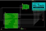
}Otro uso del pwm,usart y adc
Código:
/////////////////////////////////////////////////////////////
// USO DEL PWM CON ADC Y USART /
//Hecho por: george.manson.69 /
//contacto: george.manson.69@gmail.com /
/////////////////////////////////////////////////////////////
#include<p18F2550.h>
#include<delays.h> //tiempos
#include<timers.h> //USAREMOS INTERRUPCION POR TIMERS
#include<pwm.h> //PWM LIBRARY
#include<adc.h> //Trabajamos con ADC
#include<usart.h> //Incluimos usart
#include<stdio.h> //uso de conversiones printf
//Fuses para trabajar con 8Mhz/////////
#pragma config FOSC = INTOSCIO_EC //usamos 8Mhz internos
#pragma config PLLDIV = 5 //PLL DIV 20Mhz/5=4Mhz
#pragma config CPUDIV = OSC1_PLL2 //CPUDIV1 96Mhz/2=48Mhz
#pragma config USBDIV = 1 //tRABAJAMOS CON USB CLOCK divido en 1
#pragma config VREGEN = OFF //Trabajamos sin regulador interno 3.3v para usb
//-----------------------------------------------------------------
#pragma config FCMEN = OFF, IESO = OFF
#pragma config PWRT = ON, BOR = OFF,BORV = 0
#pragma config WDT = OFF,WDTPS = 32768
#pragma config MCLRE = ON, LPT1OSC = OFF,PBADEN = OFF,CCP2MX = ON
#pragma config STVREN = OFF,LVP = OFF,XINST = OFF,DEBUG = OFF
#pragma config CP0 = OFF,CP1 = OFF,CP2 = OFF
#pragma config CPB = ON, CPD = ON
#pragma config WRT0 = OFF,WRT1 = OFF,WRT2 = OFF
#pragma config WRTB = OFF,WRTC = OFF,WRTD = OFF
#pragma config EBTR0 = OFF,EBTR1 = OFF,EBTR2 = OFF
#pragma config EBTRB = OFF
/////Declaracion de variables ///////
/*------------------------------------------*/
unsigned int adc;
unsigned char cont;
unsigned int percent;
unsigned char flag=0;
/*------------------------------------------*/
//Prototipos de funciones ///////
/*------------------------------------------*/
void ISRTimer0(void); //Funcion de Interrupcion
void config(void); //Funcion de Configuraciones de puertos, Timer,pwm,usart,adc
/*------------------------------------------*/
//Inicio de la interrupcion por timer 0//////
// //////
//0x08 es la posicion de alta prioridad//////
//0x18 es posicion de baja prioridad //////
#pragma code Interrupcion = 0X0008
void VectorInterrupcion(void){
_asm goto ISRTimer0 _endasm
}
#pragma code
//Funcion de Interrupcion/////////////
#pragma interrupt ISRTimer0
void ISRTimer0(void){
cont++;
if(INTCONbits.TMR0IF==1 && cont==2){
flag=1;
INTCONbits.TMR0IF=0;
cont=0;
}
WriteTimer0(61629);
}
//Fin de la interrupcion //////////
/*------------------------------------------*/
//Incio de la funcion de configuracion///////
void config(void){
TRISA=0x01;
TRISC=0X80;
//Configuramos UART
OpenUSART( USART_TX_INT_OFF & //Disable Interrupts
USART_RX_INT_OFF & //----------------
USART_ASYNCH_MODE & //Modo asincronico
USART_EIGHT_BIT & //8 bit
USART_CONT_RX & //resepcion continua
USART_BRGH_HIGH ,
25); //FOSC / (16 * (spbrg + 1))
//spbrg=((FOSC/BAUD)/16)-1
//25=((8Mhz/19200)/16)-1
//Configuramos TIMER0
OpenTimer0(TIMER_INT_ON & //Interrupciones por timer0 activado
T0_16BIT & //16-bit
T0_SOURCE_INT& //Contar los ciclos internos 48Mhz/4
T0_EDGE_FALL & //~~_
T0_PS_1_256); //Preescalar =256
//Interrupcion timpo=(1/(FOSC/4))*preescalar*(65536-timer0)
// .500s=tiempo maximo
// timer0=+65536-{tiempo/[(1/(FOSC/4))*preescalar]}
WriteTimer0(61629); //Cargamos el timer0=0
//Configuramos ADC
OpenADC(ADC_FOSC_RC & //Clock Interno
ADC_RIGHT_JUST & //10bit
ADC_20_TAD , //20TAD
ADC_CH0 & //CANAL0
ADC_INT_OFF & //INTERRUPCIONES OFF
ADC_REF_VDD_VSS , //+5,GND
ADC_1ANA); //canal 0 analogo, resto digital
//Configuramos PWM
OpenTimer2(TIMER_INT_OFF &//Interrupcion timer2 OFF
T2_PS_1_16 &//preescalar = 16
T2_POST_1_1); //POst escalar=1
//
OpenPWM1(124);
//PWM period = [(period ) + 1] x 4 x Tosc x TMR2 prescaler
//PWM period = [(255)+1]x(4/8Mhz)x16
// [.001s/((4/8Mhz)*16)]-1=period
// [1/(f*(4/Tosc)*preescalar)]-1=period
OpenPWM2(124);
SetDCPWM1(127);
SetDCPWM2(127);
//Habilitamos interrupciones
RCONbits.IPEN=0; //Deshabilitamos prioridades
INTCONbits.PEIE=1; //Activamos Interrupciones por Timer0
INTCONbits.GIE=1; //Interrupciones global Activadas
}
void main(void){
OSCCON=0x70; //Oscilador a 8Mhz
//Se tiene que poner antes de todas las funciones
config(); //Funcion de configuracion
while(1){//bucle infinito
if(flag==1){ //Ha desbordado?
INTCONbits.PEIE=0; //Desactivamos TIMER0
flag=0; //TOGGLE timer0
Delay1KTCYx(1); //500uS
SetChanADC(0); //canal 0 empieza la conversion
ConvertADC(); //start convert
while(BusyADC()); //Ha terminado?
adc=ReadADC(); //lee dato
printf("ADC = %i\r\n",adc); //IMPRIME ADC
SetDCPWM1(adc); //CAMBIA VALORES DEL duty
SetDCPWM2(adc); //------------------------
INTCONbits.PEIE=1; //Activamos adc
}
}
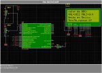
}uso de memorias eeprom 24c01B
Código:
/////////////////////////////////////////////////////////////
//                USO DEL I2C EN UNA MEMORIA EEPROM 24C01B    /
//Hecho por: george.manson.69                                /
//contacto: george.manson.69@gmail.com                        /
//Problemas:
//    Si se manda una cadena sin temporizacion osea sin tiempo
//    de transiscion puede fallar fisicamente.
//    POR EJEMPLOS
//        ENVIAR DATO                                            /
//        RETARDO DE 200mS                                    /
//        ENVIAR DATO                                            /
//        RETARDO DE 200mS                                    /
//        y asi                                                /
/////////////////////////////////////////////////////////////
#include<p18F2550.h>
#include"eepromdr.h"
#include<i2c.h>
#include<usart.h>
//#include<stdio.h>    //uso de conversiones printf
#include<delays.h>    //libreria para retardos


//Fuses para trabajar con 8Mhz/////////
#pragma config FOSC   = INTOSCIO_EC        //usamos 8Mhz internos
#pragma config PLLDIV = 5                //PLL DIV 20Mhz/5=4Mhz
#pragma config CPUDIV = OSC1_PLL2         //CPUDIV1 96Mhz/2=48Mhz
#pragma config USBDIV = 1                //tRABAJAMOS CON USB CLOCK divido en 1
#pragma config VREGEN = OFF                //Trabajamos sin regulador interno 3.3v para usb
//-----------------------------------------------------------------
#pragma config FCMEN  = OFF, IESO    = OFF
#pragma config PWRT   = ON, BOR     = OFF,BORV   = 0
#pragma config WDT    = OFF,WDTPS   = 32768
#pragma config MCLRE  = ON, LPT1OSC = OFF,PBADEN = OFF,CCP2MX = ON
#pragma config STVREN = OFF,LVP     = OFF,XINST  = OFF,DEBUG  = OFF
#pragma config CP0    = OFF,CP1     = OFF,CP2    = OFF
#pragma config CPB    = ON, CPD     = ON
#pragma config WRT0   = OFF,WRT1    = OFF,WRT2   = OFF
#pragma config WRTB   = OFF,WRTC    = OFF,WRTD   = OFF
#pragma config EBTR0  = OFF,EBTR1   = OFF,EBTR2  = OFF
#pragma config EBTRB  = OFF


//Variables a usar//////
unsigned char msje;

////////////////////////////////////////////
//Funcion de configuracion
//USART    I2C
////////////////////////////////////////////
void config(void){
    TRISC=0X80;
    //Configuramos UART
    OpenUSART(    USART_TX_INT_OFF    &    //Disable Interrupts
                USART_RX_INT_OFF    &    //----------------
                USART_ASYNCH_MODE    &    //Modo asincronico
                USART_EIGHT_BIT        &    //8 bit
                USART_CONT_RX        &    //resepcion continua
                USART_BRGH_HIGH        ,
                51);                //FOSC / (16 * (spbrg + 1))
                                    //spbrg=((FOSC/BAUD)/16)-1
                                    //51=((8Mhz/9600)/16)-1
    //cONFIGURACION DEL I2C
    OpenI2C(MASTER    ,    //I2C como master
            SLEW_ON        //a 400khz
           );
    SSPADD=4;    //CLOCK=FOSC/(4*(SSPADD+1)
                //SSPADD=[(FOSC/CLOCK)/4]-1
                //Velocidad de 400khz de 8Mhz
    INTCONbits.GIE=0;    //Desactivamos interrupciones globales
}


////////////////////////////////////////////
//FUNCION PRINCIPAL
///////////////////////////////////////////
void main(void){
    OSCCON=0x70;        //EMPIEZA A CORRER A FOSC=8Mhz

    config();

    putrsUSART("Programa para leer y escribir en una memoria eeprom \r\n");
    putrsUSART("Escribiendo....\r\n");
    Delay1KTCYx(100);
    //--------Guarda datos en la eeprom--------------///
    WriteEE(0X02,'O');
    putrsUSART("LEIENDO.....\r\n");
    //--------LEE MEMORIA EEPROM---------------------///
    msje=ReadEE(0x02);
    putcUSART(msje);
    while(1);
}
He invito a otras personas a colaborar en la programacion de este compilador tanto de uso de librerias hechas para este lenguaje ASCII, para que fuera una gran ayuda para llegar a programar correctamente estos pic18 y entender mas porque de las cosas...
.Ya que tengo unas cuantas dudas en la programacion...como son
*Como importar librerias o hacer librerias para nuestros programas
*intruccion de lcd : putrsXLCD(const char*buffer), no funciona en proteus(no aparece nada escrito)
....
Adjuntos
-
 adc.jpg215.9 KB · Visitas: 207
 -
 Control del led.jpg164.2 KB · Visitas: 143
 -
 eeprom.jpg197.7 KB · Visitas: 126
 -
 pwmrs2.jpg129.6 KB · Visitas: 129
 -
 pwmrs23.jpg240.2 KB · Visitas: 122
 -
P1.zip15.9 KB · Visitas: 375
-
P2.zip60.7 KB · Visitas: 253
-
P3.zip92.4 KB · Visitas: 248
-
P4.zip111.3 KB · Visitas: 249
-
P5.zip46.5 KB · Visitas: 243
-
P6.zip69.2 KB · Visitas: 241
-
P7.zip67.9 KB · Visitas: 268