Notaste el detalle que el usuario a quién le pides información no entra a la comunidad desde el 08 Feb 2008
Lo tome de:
Current Loop Application Note
Current Loop Application Note
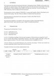
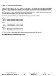
Introduction
The purpose of this current loop application note is to introduce the reader to the physical aspects of 20 mA current loop communications.
Until the early 1960's, military teleprinters used 60 ma current loops to communicate over long distances. In 1962, the Model 33 teletype was introduced and 20 mA current loop interfaces became widely used. Throughout the 60's, 70's, and early 80's, 20 mA current loop interfaces were applied in many types of equipment. Current loop interfaces became popular at this time because they offered the most cost effective approach to long distance, noise immune data transmission. The 20 mA current loop is suitable for distances to 2000 feet at data rates up to 19.2k baud with careful attention to interface design. It can be used at longer distances when data rates are as low as 300 baud.
When the EIA 422 Standard (December 1978) and the EIA 485 Standard (April 1983) brought forth the application of balanced differential digital data transmission, the popularity of 20 mA current loop rapidly diminished.
The Basics of Current Loop
2.1 Full-duplex 20 mA Circuit
Figure 1 is a full-duplex 20 mA current loop circuit. Simultaneous two-way communications is possible with this circuit. Two 20 mA current generators are necessary with this circuit. It is possible to have one of the two current generators in one current loop interface and the other current generator in the other interface. For example, the original IBM PC serial adapter card had a current loop interface that contained only one current generator. When you made a correct connection to this current loop interface, the second current loop device would need to provide one current loop generator.
Figure 1: Full-duplex 20 mA Circuit
2.2 The Simplex 20 mA Circuit
Figure 2 is a diagram of a simplex 20 mA current loop circuit. The fundamental elements of a 20 mA current loop are a current source, a current switch, and a current detector. The transmitter is the current switch and the receiver is the current detector. The interface that contains the current source is called the active unit and all other units are referred to as passive units. Figure 3 is a diagram of the levels in an RS-232 interface and how they relate to the presence and absence of current in a 20 mA current loop circuit. In a 20 mA loop the current flows when the loop is idle (no data being transmitted). In a simplex type circuit a number of transmitters and receivers are put in series in a current loop. As long as only one transmitter sends data, all receivers receive the data.
(Only one device can transmit at a time)
Figure 2: Simplex 20 mA Circuit
Figure 3: Comparison of signal levels in an RS-232 Circuit and a 20-mA Current Loop Circuit
2.3 Problems with 20 mA Current Loop
The main problem with 20 mA current loop is that there is no mechanical or electrical standard defined for this interface. This makes every interface somewhat unique and the user must know some of the technical details about the circuits used in the interface.
Figure 4: Simplified One Direction Current Loop
Figure 4 is a simplified one-way current loop implemented with two optocouplers, a voltage source, and a resistor. Optocoupler U1 is the transmitter and optocoupler U2 is the receiver. The value of the loop current in this circuit is:
I loop = (Vs - V transmitter -V receiver)/Rs
for typical optocouplers
When turned ON:
V transmitter (U1) = 0.2 V
When input LED is conducting:
V receiver (U2) = 1.8 V
If Vs = 12 volts & Rs = 470 ohms then
I loop = (12V - (0.2V + 1.8V))/470 ohms
I loop = 10V/470 ohms = 21.3 mA
If we changed Vs = 60 V and left Rs = 470 then
I loop = (60V -(0.2V + 1.8V))/470 ohms = 123 mA
If we changed Vs = 5 V and left RS = 470 ohms then
I loop = (5V - (0.2V + 1.8V)/470 ohms = 6.4 mA
The point of showing these different calculations is to demonstrate that the loop currents circuit can vary by considerable amounts, if Vs is varied. Likewise, if Rs was changed the loop currents could also vary considerably. The only way to determine that currents are near 20 mA is to examine the circuit in detail.
2.4 Current Regulation in Current Loops
Several methods can be used to control the amount of current in a current loop circuit. This section will illustrate several common methods of regulating the current in a current loop.
2.4.1 Constant Current Generator Current Source
Figure 5 is a circuit that uses a linear voltage regulator integrated circuit to serve as a constant current source. Almost any fixed or adjustable voltage regulator can be used. The example shown in Figure 6 uses an LM317 adjustable regulator because is provides a low amount of voltage drop (3 volts) across the current regulator circuit. For example, if Vs was 12 volts in this circuit, then the maximum voltage that the constant current regulator could drive would be 9 volts. The 62 ohm, Rg resistor sets the regulator current because there is an internal voltage reference in the LM317 between VO and the ADJ pins of 1.25 volts.
Figure 5: Constant Current Generator for a 20 mA Current Loop
In a current loop, the sum of all the voltage drops across all the devices must be less than the voltage source, Vs driving the loop. Each device in the current loop whether it is a transmitter (current switch) or receiver (current detector) has some voltage drop across it. For instance, a typical transistor switch can have typically 0.2 volts drop across it. For most of B&B Electronics converters, the voltage drop across the transmitters can be as much 2.3 volts when the switch is turned ON. The reason for this is that the transmitter switch must provide for the reverse bias of the internal photo detector diode inside the optocoupler. An optocoupler used as a current detector will have from 1.2 to 2.0 volts drop across it.
Figure 6: Current Limiter built into Transmitter
2.4.2 Transmitter Current Limiter
Some current loop interfaces incorporate current limiting into the transmitter (current switch) itself. Figure 6 is an example of a circuit that has built-in current limiting so that the loop current cannot exceed 20 mA. In this circuit Rg provides a source of bias current for Q2 so that if the loop current tries to exceed 20 mA Q2 will shunt Q1 base bias current so that Q1 will not conduct more than 20 mA.
Figure 7. Current Limiter built into Receiver
2.4.3 Receiver Current Limiter
The circuit shown in Figure 7 is used not to regulate the loop current, but to regulate the maximum emitter current in the optocoupler, U1. This is done because some optocouplers require less than 20 mA to operate at maximum speed. Transistor Q1 is used to shunt some of the loop current around the emitter of optocoupler, U1.
3.0 Current Loop Interface Connections
To connect our converter to an existing current loop port, you must first determine if the port is active or passive. What this means is: does the port have an internal power supply that provides the current (active) for the transmitter, the receiver, or both (transmitter and receiver). The simplest way to determine this is to break the loop (disconnect it) and see if there is any DC voltage across the output or input pairs. If you have access to the instruction manual for the unit you can also look in there for the information.
Current loop interfaces normally consist of four wires. They are usually labeled T+, T-, R+, and R-. T+ and T- are the transmit plus and transmit minus lines and data is output from that device on those lines. The R+ and R- lines are the receive plus and receive minus lines and data is input into that device on these lines. Interconnection of the two current loop devices is different depending on whether your unit is active or passive.
3.1 Connection to an Active Current Loop Port
Connection to an active current loop port is very simple. Your units T+ and T- lines go to our units R+ and R- lines. And your units R+ and R- lines go to our units T+ and T- lines. See the following drawing.
Figure 8. Connection to an Active Current Loop
3.2 Connection to a Passive Current Loop Port
Connection to a passive current loop port is a little harder. You must use a 12 VDC power supply with the 470 ohm resistors inside of our converter to "create" a 20 ma current source. See the following drawing.
Figure 9. Connection to a Passive Current Loop
3.3 Interconnection of 2 Current Loop Converters
Interconnection of two B&B current loop converters also requires the use of a 12 VDC power supply since they are both passive port. See the following drawing.
Figure 10. Interconnection of Two Current Loop converters
4.0 What Isn't Digital Current Loop
4.1 4 to 20 mA Analog Current Loop
The diagram shown in Figure 11 is an analog 4 to 20 mA current loop. This circuit is mentioned here because it is sometimes confused with 20 mA digital current loop. The purpose of 4 to 20 mA analog current loop is to transmit the signal from an analog sensor over some distance in the form of current signal. Only two wires are required to send the analog signal and also supply power to the sensor. A loop supply voltage (24 volts in Figure 11) is used to power the remote sensor. The remote sensor regulates the loop current such that the loop current represents the value of the parameter being measured by the sensor. A series resistor RL at loop power supply converts this current to a voltage that can be used by the electronics to record or distribute the parameter being measured.
Figure 11. 4 to 20 mA analog current loop
4.2 HART® 4 to 20 mA Current Loops
Figure 12 is another example of a type of 4 to 20 mA combined analog & digital current loop. This current loop uses HART® Communications protocol. The HART® (Highway Addressable Remote Transducer) protocol is used for SMART remote transducers that are compatible with 4 to 20 mA analog current loops but also have digital communications on the same two wires. This is accomplished by superimposing a two-tone Frequency Shift Keyed (FSK) digital current signal on the 4 to 20 mA analog signal.
Figure 12. 4 to 20 mA analog current loop with digital communications using HART protocol