Follow along with the video below to see how to install our site as a web app on your home screen.

Nota: This feature currently requires accessing the site using the built-in Safari browser.

INTERNAL VOLTAGE REFERENCE
The reference is designed to be adjustable and develops a nominal 1.25V between the REF OUT (pin 7) and
REF ADJ (pin 8) terminals. The reference voltage is impressed across program resistor R1 and, since the
voltage is constant, a constant current I1
then flows through the output set resistor R2 giving an output voltage of:
Since the 120μA current (max) from the adjust terminal represents an error term, the reference was designed to
minimize changes of this current with V
+ and load changes.
CURRENT PROGRAMMING
A feature not completely illustrated by the block diagram is the LED brightness control. The current drawn out of
the reference voltage pin (pin 7) determines LED current. Approximately 10 times this current will be drawn
through each lighted LED, and this current will be relatively constant despite supply voltage and temperature
changes. Current drawn by the internal 10-resistor divider, as well as by the external current and voltage-setting
divider should be included in calculating LED drive current. The ability to modulate LED brightness with time, or
in proportion to input voltage and other signals can lead to a number of novel displays or ways of indicating input
overvoltages, alarms, etc.
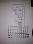
Hola! Estoy haciendo un circuito parecido a este, soy nuevo en esto de la electronica. En mi circuito (foto) al encerderse cualquier led menos el primero, ese diodo, no hace que el led o los leds de arriba se enciendan con menor intensidad? Que deberia hacer para que todos se enciendan por igual haciendo este patrón:Vuelvo a subir la imagen que hoy no pude...
Creo que lo mejor es el 555 con el 4017!!
Aca te dejo una idea basica, a la salida irian unos transistores y de ahi a las lamparas
Ver el archivo adjunto 159149
Como ves, cuando enciende la primer salida (la de arriba) solo enciende la primer lampara, al pasar a la segunda salida, enciende tambien la primera a traves del diodo puente, y cuando enciende la tercera, pasa lo mismo con las dos anteriores, la cuarta salida iria al reset, con lo que todo vuelve a empezar.
Listo, asunto solucionado.
Bueno gracias, voy a buscar por el foroTal como lo has puesto que buscas? porque si quieres que se encienda primero uno luego dos y así hasta 10, estas utilizando el circuito equivodado, para eso o lo haces discreto o utilizas por ejemplo el LM3914 y utilizas una rampa en su entrada, utiliza el buscador hay circuitos publicados en el foro